A custom extruded heat sink may satisfy a thermal simulation and still be difficult or unnecessarily expensive to manufacture. Its aluminum cross-section must pass through a die, maintain an acceptable shape after extrusion and cooling, and leave enough access for any later CNC machining.
That is why design for manufacturability (DFM) should begin before an extrusion die is approved. Fin height, fin thickness, channel spacing, base geometry and mounting details should be evaluated as a system—not simply as dimensions on a CAD drawing.
This guide examines the decisions that most often affect extrusion feasibility and cost. It also draws on two actual XINXIANG tooling projects, including a high-density fin heat sink and a complex U-shaped finned profile, to show how tooling and finished geometry are connected.
Start With the Finished Heat Sink, Not Just the Profile
Aluminum extrusion produces a continuous cross-section. Fin count, fin roots, base thickness, straight channels and any continuous mounting rails are defined by the extrusion die. The heat sink is then cut to length, and additional features may be machined as required.
This distinction matters. A continuous slot used along every part may be economical to extrude. A localized threaded hole, mounting pocket or clearance cut is usually better created after extrusion. Designing the cross-section without considering the finished-part operations can create avoidable workholding, machining or tooling problems.
Before finalizing the cross-section, define the heat load, available footprint, airflow direction, mounting surface and expected quantity. A geometry change that looks trivial in CAD can affect the extrusion die, the finished heat sink and the project’s total production cost.
Thin Fins and Narrow Gaps: When Geometry Becomes a Tooling Challenge
Increasing fin height or adding more fins can increase nominal surface area. Yet a high-density heat sink also places greater demands on the die and the extrusion process. Narrow channels in the aluminum profile correspond to slender or deep steel features in the tooling. Those features must withstand extrusion pressure while helping maintain consistent metal flow.
A useful descriptive measure is nominal fin height divided by fin thickness. For example, a 30 mm-high fin that is 2 mm thick has a ratio of 15:1. It is not a universal extrusion limit: two profiles with the same ratio may behave differently because of overall width, channel geometry, alloy, die construction and press capability.
Fin spacing also affects the actual cooling system. Narrower gaps may increase available surface area but can raise airflow resistance, particularly through long channels. If a fan cannot deliver the needed pressure, additional fins may fail to improve thermal performance. For the airflow side of this trade-off, see our heat sink fin spacing guide.
XINXIANG Tooling Example: High-Density Thin-Fin Extrusion
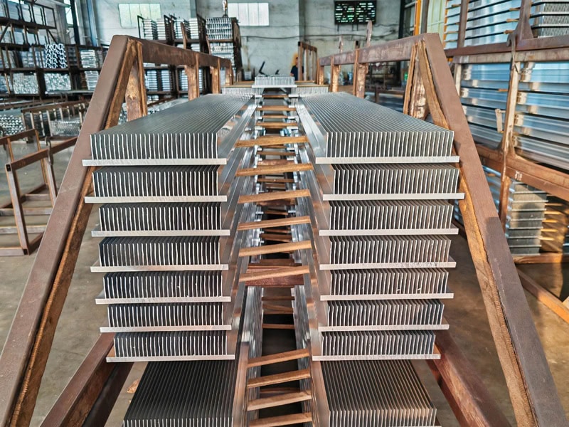
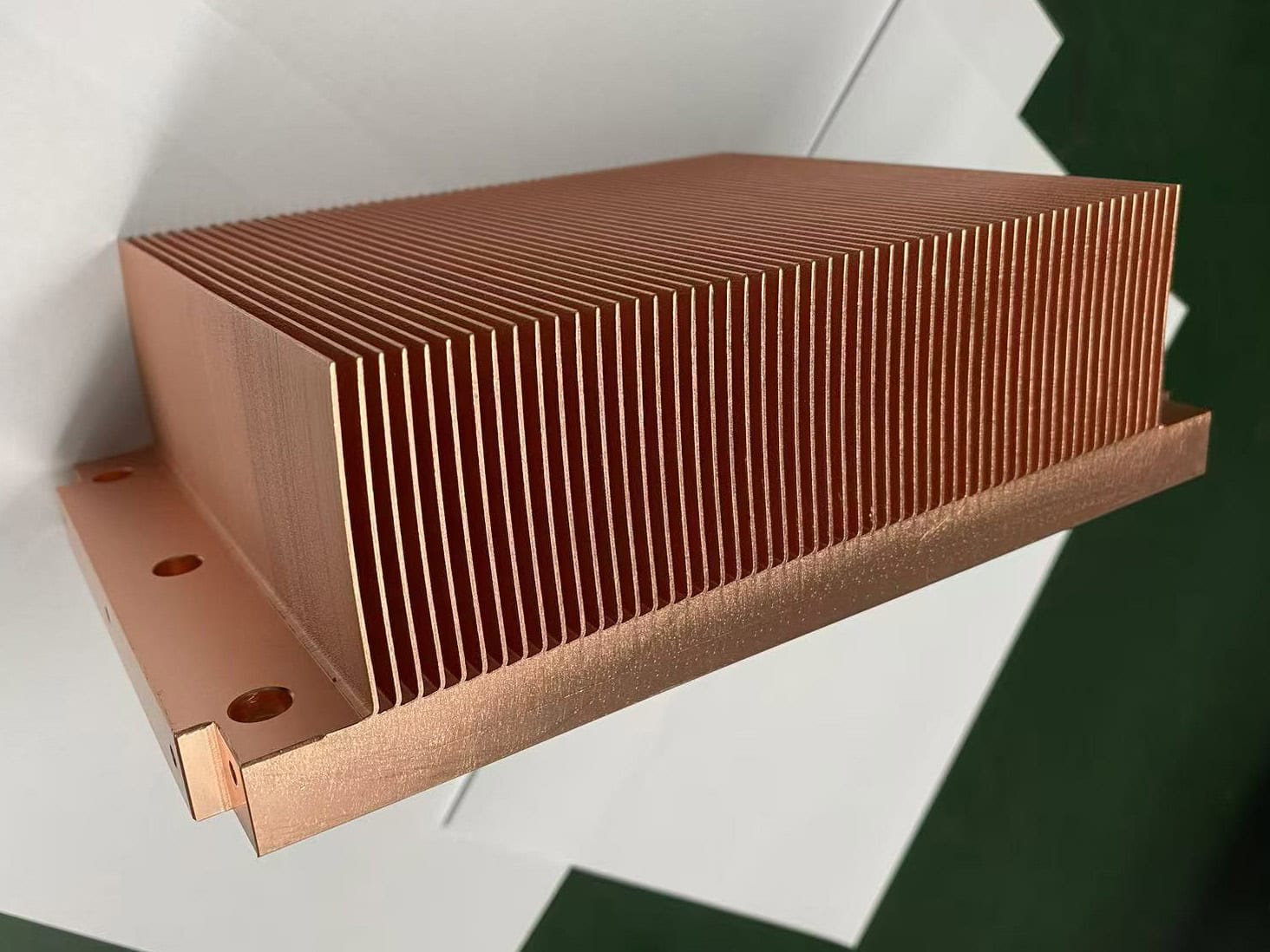
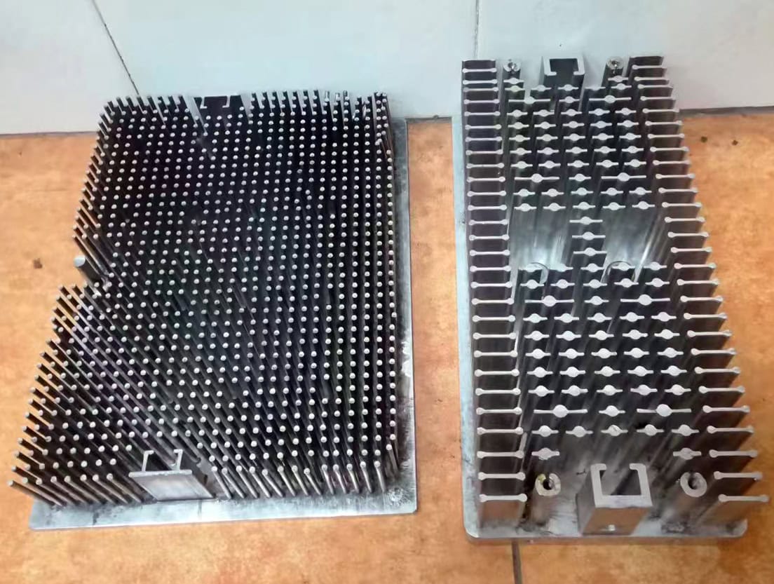
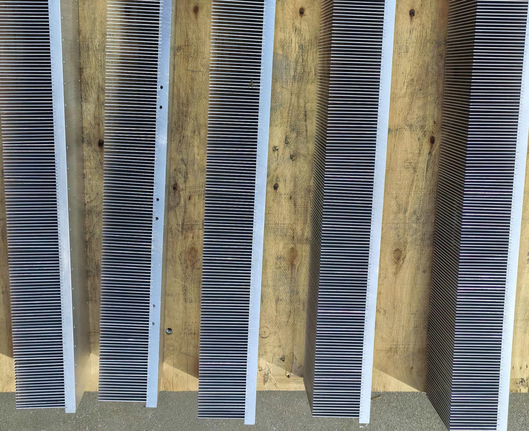
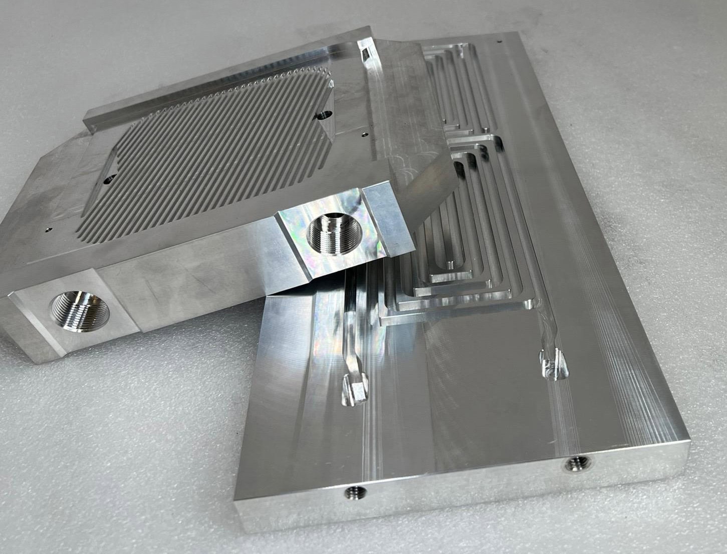
The photographs below come from a XINXIANG extrusion tooling project. They show the die face and high-density extruded aluminum heat sink sections with many closely spaced fins. The pairing illustrates the relationship between the intended fin geometry and the die features required to form it.
For this type of design, a DFM review should pay particular attention to fin-root geometry, the width and depth of die openings, alloy selection and expected dimensional consistency. The photograph is evidence of a real tooling and extrusion project—not a thermal test, an approved tolerance report or proof of a universal maximum fin ratio.

XINXIANG tooling project: an extrusion die and high-density aluminum heat sink profiles with thin, closely spaced fins.
Balance Base Thickness, Fin Roots and Metal Flow
The base must spread heat from the electronic component and provide adequate support for mounting and machining. Making it thicker can improve heat spreading for some layouts, but also increases weight and aluminum consumption. Under a fixed overall height, a thicker base can leave less height for the fins.
In extrusion, the transition from a thick base to thin fins also affects the distribution of metal in the cross-section. Large abrupt changes in thickness may require additional die-flow balancing and can contribute to variation or distortion. Well-considered fin-root radii, tapers and transitions may help, provided the thermal and mechanical requirements are still met.
Symmetrical profiles can be easier to balance, but symmetry is not mandatory. Offset heat sources, side flanges or asymmetric mounting features may be necessary. The manufacturing review should distinguish essential features from details that can be simplified without changing the function.
What the Extrusion Die Must Accommodate
The die is not just a flat negative image of the profile. Its openings and supporting steel must withstand forming loads while shaping aluminum flow. The overall cross-section size, often assessed using its circumscribing circle diameter (CCD), also helps determine suitable press capacity.
Deep narrow grooves, thin steel tongues, multiple cavities and semi-hollow features can make a die more demanding. The Aluminum Extruders Council emphasizes balanced wall thicknesses, manageable tongue geometry, symmetry where practical and smooth transitions as useful extrusion-design principles. These are design guidelines, not absolute limits for every press and die.
XINXIANG Tooling Example: A Complex U-Shaped Finned Profile
The second real project shows a CAD tooling view, a machined extrusion die and the resulting U-shaped finned aluminum section. Unlike a conventional flat-base heat sink, this section combines side fins with a deep central opening and additional internal voids.
The example illustrates why the complete cross-section must be reviewed. Designers need to consider the die support around openings and cavities, wall balance, fillet transitions and the available press. We do not present this case as a measured cost-saving result or claim that a specific redesign was made; the value lies in showing the actual connection between design geometry, manufactured tooling and the extrusion.
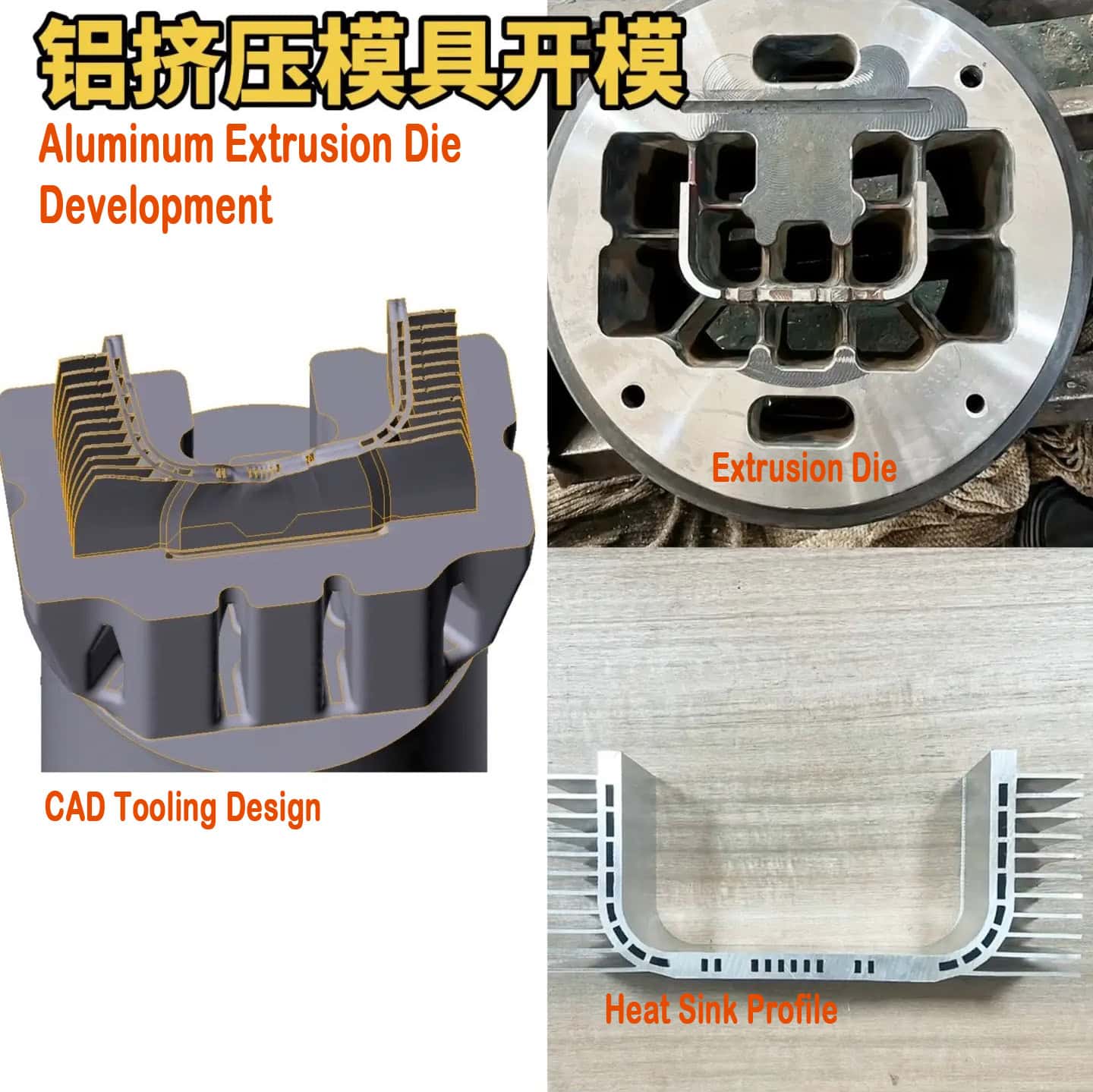
XINXIANG manufacturing project: CAD tooling design, machined extrusion die and matching U-shaped finned aluminum profile.
Specify Alloy and Tolerances for the Function
Alloy 6063 is frequently used for aluminum heat sink extrusions because of its extrudability and useful balance of thermal, mechanical and finishing properties. Other alloys, including selected 6000-series grades, may be appropriate when mounting strength or other requirements are more demanding.
Do not choose an alloy solely from one thermal-conductivity value. Conductivity can depend on alloy and temper, while extrusion behavior, surface finish and mechanical strength also affect suitability. Confirm the material and temper against the actual application before tooling approval.
Likewise, distinguish as-extruded tolerances from tolerances after cutting or machining. Fin dimensions, channel width, straightness, twist and section flatness are not controlled in the same way as drilled holes or a CNC-machined device mounting face. The current ANSI H35.2M dimensional tolerance standard provides an industry framework, but a project drawing should identify the specific critical dimensions and inspection conditions.
A nonfunctional fin tip usually does not need the same control as a semiconductor mounting surface. Specifying unnecessarily tight tolerances everywhere can increase inspection, machining and rejection costs without improving cooling.
Plan CNC Machining Before the Die Is Finalized
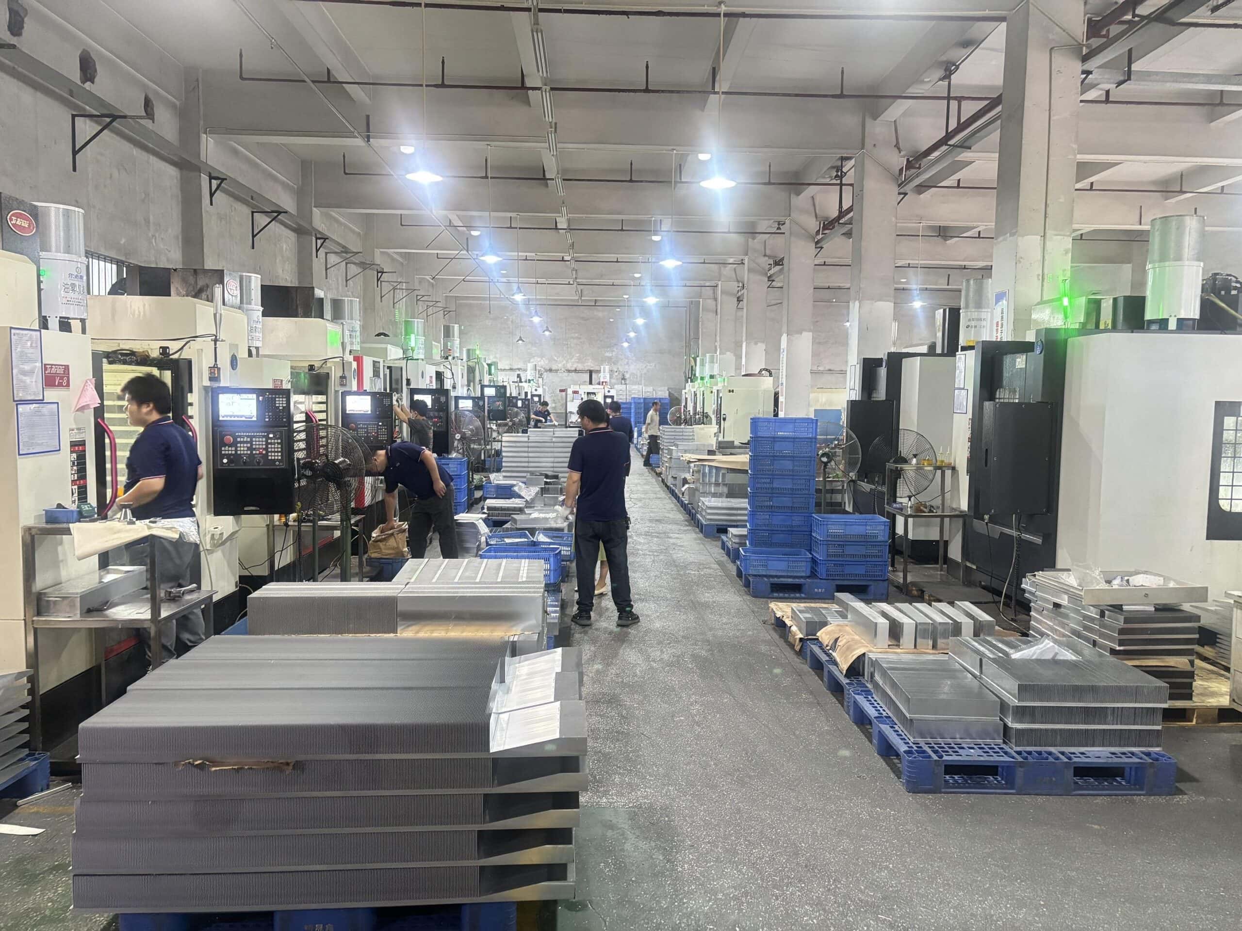
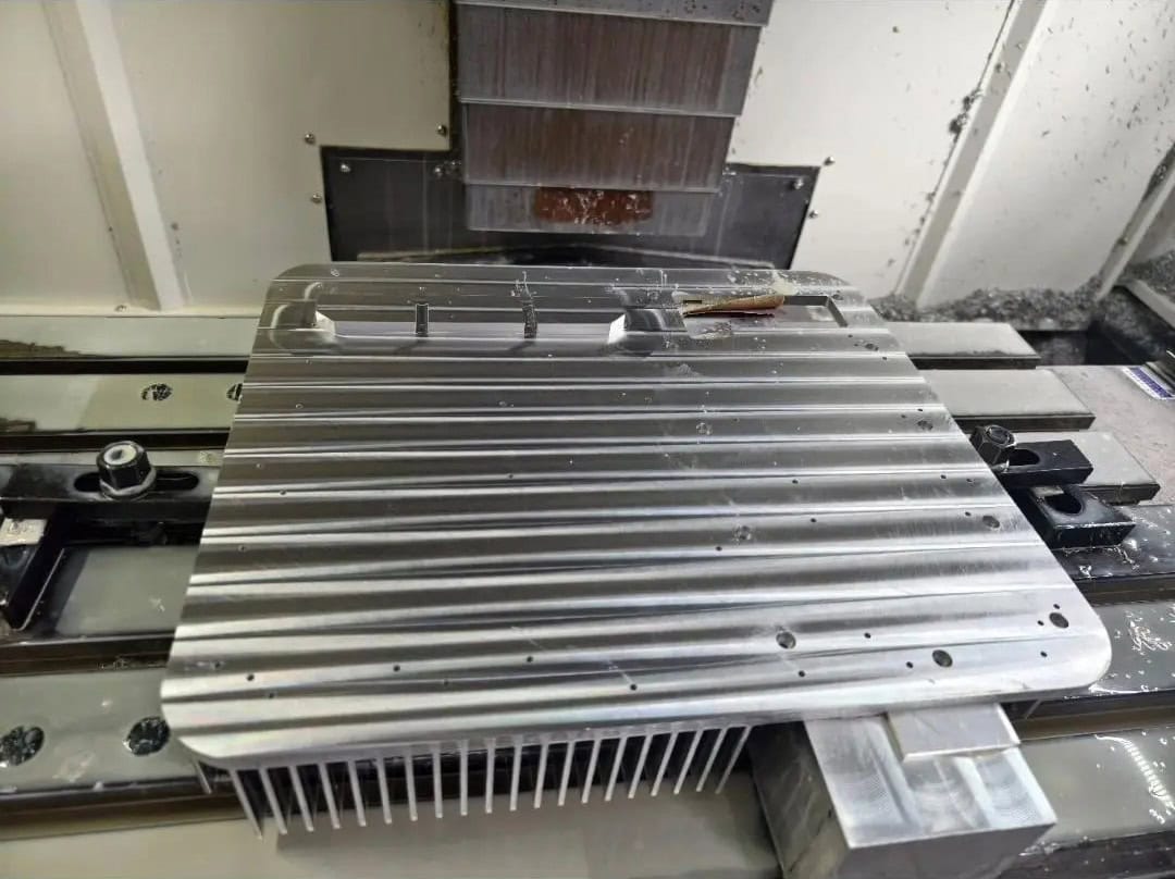
Most custom extruded heat sinks require secondary operations. Typical examples are cutting to length, drilling, tapping, milling pockets or slots, and machining the mounting face. A good DFM review decides which features belong in the continuous extrusion and which should be created afterward.
Consider tool access early. Tall fins can obstruct a drill or milling cutter; thin fins can deform under poor clamping; and a thin base may need additional support during machining. Local mounting details should therefore be reviewed together with the cross-section, not added as an afterthought.
For power electronics cooling, when a power module needs a precisely controlled interface, finish-machining may be appropriate. But the correct flatness and surface finish must follow the device manufacturer’s assembly requirements and the selected thermal interface material. Our heat sink base flatness and surface roughness guide includes a separate real manufacturing example.

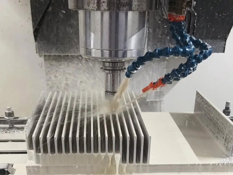
Secondary CNC machining on an extruded aluminum heat sink. Mounting and access features should be considered during the original profile design.
Existing Tooling or a New Custom Extrusion Die?
An existing profile can eliminate a new extrusion die charge. XINXIANG maintains a heat sink extrusion profile library where engineers can compare the overall width, height and base thickness of existing sections.
For example, two published profiles share a nominal width of 200 mm but have quite different envelopes:
- XHS-200001: 200 mm wide, 40 mm overall height, 10 mm base thickness.
- XHS-200008: 200 mm wide, 83 mm overall height, 16 mm base thickness.

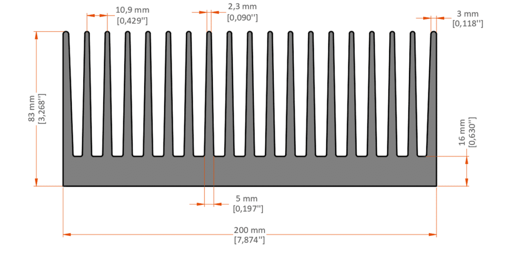
The larger overall height and thicker base of the second profile change the space available for fins and the material distribution in the cross-section. This does not prove that one is easier to extrude or performs better thermally; a meaningful comparison would also require fin geometry, length, alloy, airflow and application data.
Existing tooling is a useful first option for prototypes and lower quantities. However, if the final part needs extensive CNC removal on every unit, a new custom extrusion designed for repeat production may ultimately be more economical. Compare die charge + material + cutting + machining + finishing + inspection, rather than just the upfront tooling fee.
For guidance specifically on selecting a pre-existing die, see How to Choose a Heat Sink Extrusion Profile for Your Project. This article instead focuses on assessing the manufacturing feasibility of a proposed design.
A Short DFM Review Before Tooling Approval
These checks are intended to prompt engineering discussion, not to impose universal extrusion limits.
| Design detail | Manufacturing concern | DFM question |
|---|---|---|
| Tall, thin fins | Demanding die features and fin dimensional control | Can modest changes to height, thickness or root geometry improve extrusion stability? |
| Very narrow fin channels | Deep and slender die steel features; pressure drop in service | Is the specified gap necessary for the actual airflow and fan pressure? |
| Thick base with very thin fins | Metal-flow imbalance and die-design complexity | Can transitions or local thicknesses be improved without compromising heat spreading? |
| Deep U-shaped / semi-hollow details | Die-tongue support and tool complexity | Can the opening, radii and cavities be designed for reliable tooling? |
| Fine mounting holes and pockets | Features cannot always be formed economically along the extrusion direction | Should they be CNC machined after cutting? |
| Tight tolerances everywhere | Potential extra inspection, straightening or machining | Which dimensions and surfaces actually control product function? |
| Existing die with extensive machining | Recurring CNC cost may outweigh saved die charge | At expected volume, is a new profile more economical? |
When Another Manufacturing Process Makes More Sense
Sometimes the most economical change is not another modification to the extrusion die. If the fin structure requires very thin, dense fins in a compact envelope, skiving may be worth evaluating. If the required assembly is particularly wide or needs independently manufactured tall fins, bonded fin construction may be another option.
These alternatives also bring process-specific trade-offs. Skiving is a one-piece machining process; bonded fin construction introduces a separate fin-to-base joint and associated assembly quality controls. The decision should follow the thermal design, available manufacturing routes and total finished-part cost—not simply the largest possible fin area.
What to Include in a Custom Extrusion RFQ
To make a useful manufacturing review possible, send the cross-section and the finished part requirements together. The most helpful information includes:
- Section drawing: width, height, base thickness, fin count, fin thickness, pitch, internal features and important radii.
- Finished-part drawing: cut length, hole locations, mounting features, machining access and critical tolerances.
- Thermal application: heat load, device contact area, ambient temperature, airflow conditions and allowable temperature limits.
- Material and finish: proposed alloy/temper, anodizing or other surface treatment, and any masked functional faces.
- Commercial requirements: prototype quantity, annual production estimate, inspection expectations and target timing.
An accurate 2D section is often enough to begin a die-feasibility conversation. A finished 3D model becomes especially useful when the part includes machining that is not continuous along the extrusion direction.
Before You Approve an Extrusion Die
The strongest custom extruded heat sink design is not simply the one with the greatest fin surface area. It is a design that meets the thermal requirement while allowing practical die construction, consistent extrusion, accessible CNC operations and appropriate quality control.
Our real tooling photographs illustrate two important situations: dense thin fins that place demands on die geometry, and a complex U-shaped profile where the internal cavities and overall section must be considered together. They are valuable manufacturing examples, but they are not substitutes for project-specific engineering validation.
XINXIANG can review your proposed heat sink cross-section, compare it with available tooling, and evaluate extrusion, machining and finishing requirements. Send us your drawing and expected quantity for a custom manufacturing review and quotation.
Technical References
- Aluminum Extruders Council — Extrusion Design Tips: symmetry, wall thickness, transitions, grooves and ribs.
- Aluminum Extruders Council — Key Design Considerations: CCD, weight per foot, shape constraints, die complexity and press selection.
- The Aluminum Association — Understanding Aluminum Extrusion Tolerances: interpretation of profile dimensional tolerances.
- Eaton — Extrusion Technology Overview: background on extruded heat sink fabrication.