
When engineers need more cooling from an air-cooled heat sink, adding more fins may seem like an obvious solution. More fins create more surface area, and more surface area can potentially transfer more heat to the surrounding air.
But there is a limit.
As fins are packed more closely together, the channels available for airflow become narrower. Under natural convection, this can interfere with the buoyancy-driven movement of warm air. Under forced convection, tighter channels increase airflow resistance and can reduce the amount of air a fan actually delivers through the heat sink.
The result is an important design principle:
The best heat sink is not necessarily the one with the most fins. It is the one that provides effective surface area for the airflow that is actually available.
For engineers and buyers, heat sink fin spacing should therefore be evaluated together with airflow, fin length, fin height, manufacturing process, and the overall system—not as an isolated dimension.
What Is Heat Sink Fin Spacing?
Fin spacing, also called the fin gap, is the open distance between two adjacent fins.
It is different from fin pitch.
Fin spacing = open gap between adjacent fins
Fin pitch = fin thickness + fin spacing
Reducing the spacing allows more fins to fit within the same heat sink width. This increases nominal surface area, but it also changes how easily air can move through the fin channels.
That tradeoff is why there is no universal “best” fin spacing.
Published heat sink design guidance shows that optimum spacing depends strongly on airflow velocity and the fin length in the direction of airflow. A geometry that works well for a short forced-air heat sink may therefore be poorly suited to a long passive heat sink.
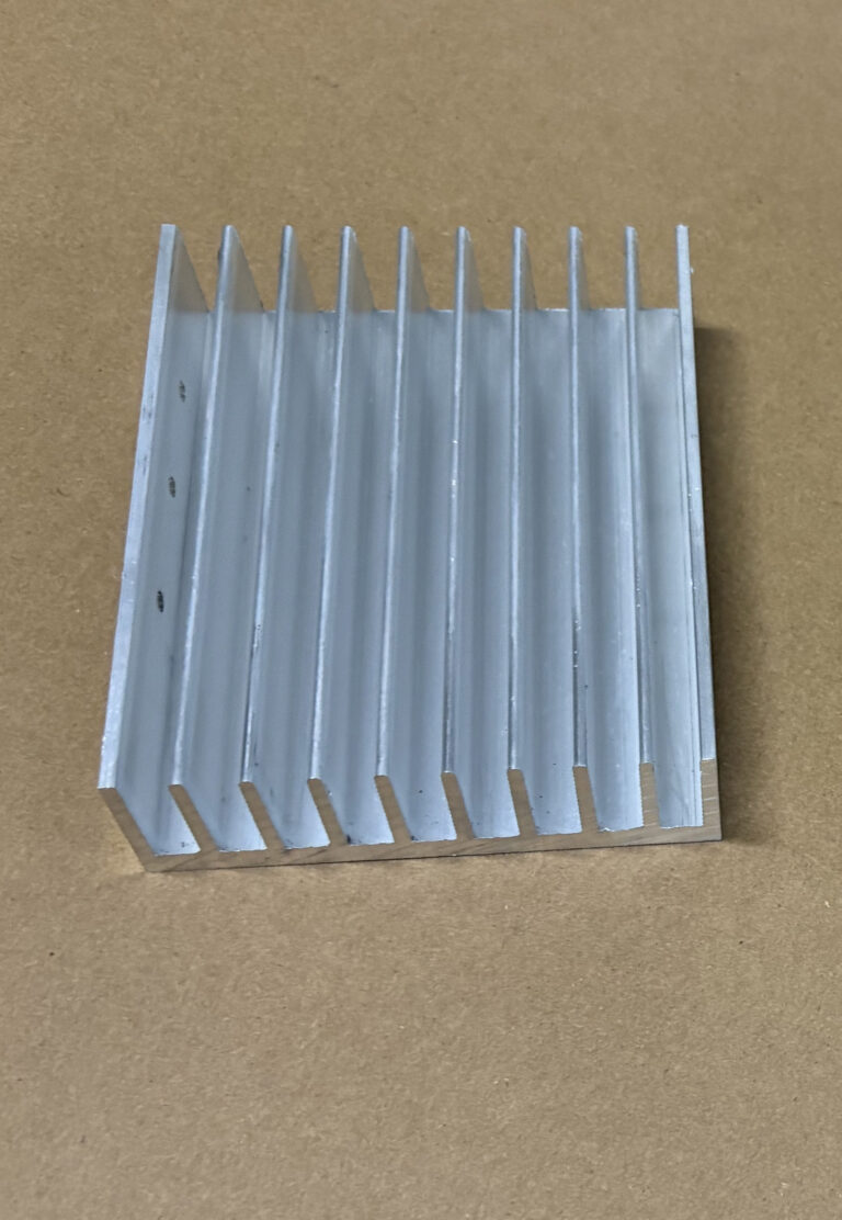
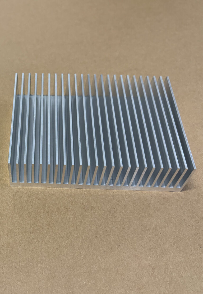
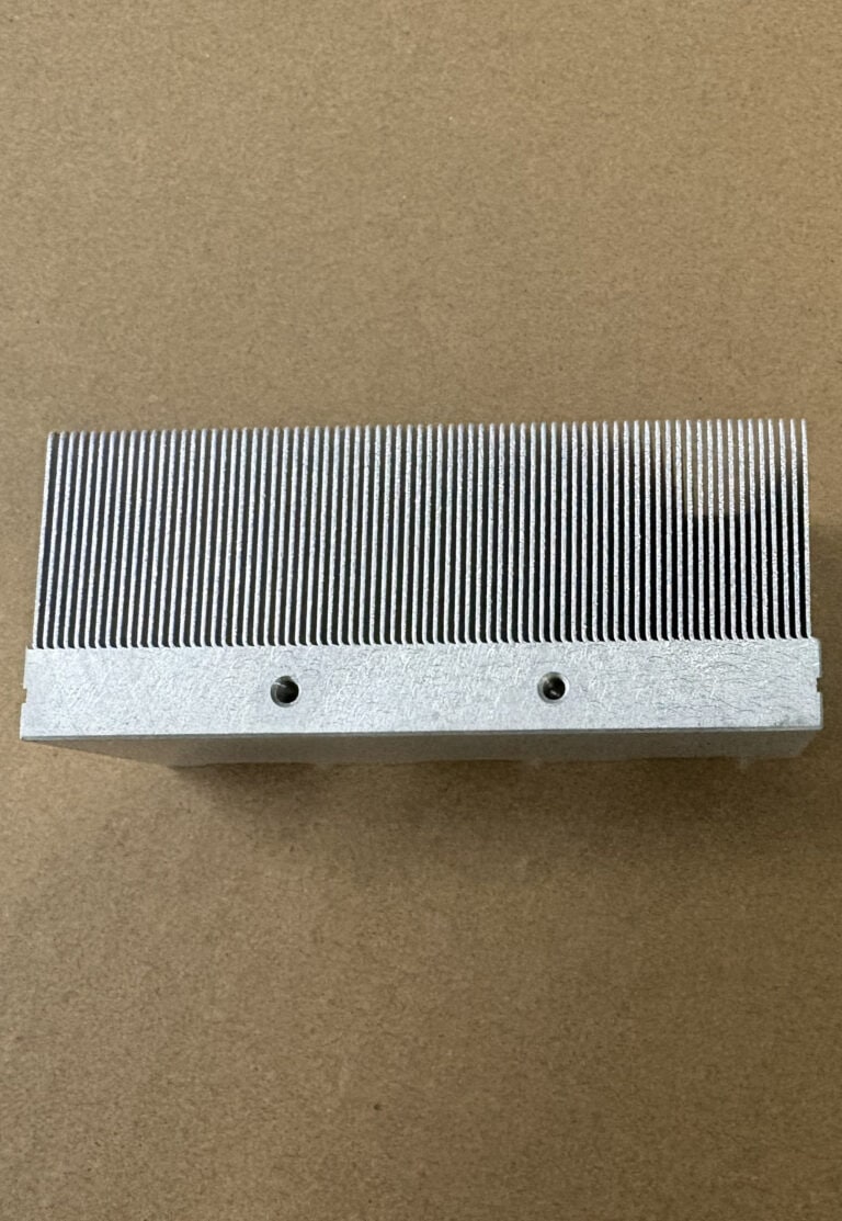
Examples of different fin-spacing geometries; actual spacing should be selected for the specific airflow and system conditions.
Why More Fins Can Eventually Hurt Performance
A heat sink needs both surface area and air movement.
If the fins are spaced very widely, airflow resistance is low, but the heat sink may not provide enough fin surface.
If they are packed extremely closely, the heat sink gains surface area, but some of that additional area may become less effective because airflow through the channels becomes more difficult.
The optimum lies somewhere between these two extremes.
Where that point occurs depends on the cooling environment. Natural convection, low-velocity forced airflow, and higher-pressure forced airflow can all favor different fin geometries.
This is why fin count alone is a poor way to compare two heat sinks.
Natural Convection Usually Needs More Open Fin Channels
A passive heat sink relies mainly on buoyancy rather than a fan.
As air next to the fins warms, its density decreases and it rises. Cooler air then enters the fin channels to replace it. This continuous movement carries heat away from the heat sink.
The spacing between the fins influences how well this flow can develop.
A thermal boundary layer forms along each heated fin surface. When adjacent fins are placed too close together, these boundary layers interact and the natural upward flow through the channel can become less effective.
Adding another fin in this situation increases metal surface area, but it may not create a proportional increase in useful heat-transfer area.
This is one reason passive heat sinks commonly have more open fin channels than compact forced-air designs.
Orientation Matters Too
Fin spacing alone cannot fix poor orientation.
For many straight-fin passive heat sinks, the channels should be positioned so that heated air can rise through them with as little obstruction as possible.
Enclosures, horizontal mounting, nearby components, walls, and restricted inlet or outlet openings can all change the real convection path.
For natural-convection projects, engineers should therefore evaluate fin spacing, orientation, fin length, and surrounding clearance together.
Forced Air Can Support Closer Fin Spacing
With an active heat sink, a fan or blower supplies the airflow.
Because air is being driven through the fin channels, closer spacing can often be used than would be practical under natural convection. This is one reason many high-density skived heat sinks are designed around forced-air cooling.
But forced airflow does not eliminate the spacing problem. It changes it into a pressure-drop problem.
As fin spacing decreases, resistance to airflow generally increases. Longer channels, dense fin arrays, filters, grilles, ducts, and other restrictions can further increase total system resistance.
The fan must overcome that resistance.
Do Not Design Around Free-Air CFM Alone
A common mistake is to select a fan based only on its advertised airflow rating.
The maximum CFM shown for a fan is typically measured under very low resistance. Once the fan is installed behind a dense heat sink, grille, filter, or duct, actual airflow may be significantly different.
A fan has a pressure-flow curve, while the heat sink and enclosure create a system resistance curve.
The point where these curves intersect determines the actual operating airflow.
This means two heat sinks with the same external dimensions can operate very differently with the same fan if one has much narrower fin channels.
For forced-air thermal design, the useful question is therefore not:
“How much airflow can this fan produce?”
but:
“How much airflow will this fan produce through this heat sink and the complete system?”
That distinction becomes increasingly important as fin density rises.
Fin Length Changes the Required Spacing
Fin spacing should also be considered together with the length of the heat sink in the airflow direction.
As air travels through a fin channel, it absorbs heat. A longer channel also creates more frictional resistance than a shorter one.
Consequently, a fin spacing that works well for a short heat sink should not automatically be copied to a much longer design.
Heat sink design guidance generally shows that optimum fin spacing increases as the flow length becomes longer when other conditions are comparable.
This has an important manufacturing implication for extruded heat sinks.
An extrusion profile may have a fixed cross-section, but it can be cut into many different lengths. The same profile therefore does not necessarily provide identical thermal behavior when used as a 50 mm-long heat sink and a 300 mm-long heat sink.
The final cut length and airflow direction should be considered when selecting an existing profile or designing a new extrusion.
A Practical Way to Think About Fin Spacing
The table below summarizes several common design situations. These are general tendencies rather than fixed dimensional rules.
| Cooling Condition | Fin-Spacing Tendency | Main Reason |
|---|---|---|
| Natural convection | Generally more open | Allows buoyancy-driven airflow to develop between fins. |
| Low-pressure forced air | Moderate spacing | Must balance additional surface area against airflow resistance. |
| Higher-pressure forced air | Closer spacing may be practical | Available pressure can drive air through denser fin channels. |
| Longer airflow path | Spacing requires closer review | Longer channels increase flow resistance and warm the air along the path. |
| Restricted enclosure | Do not evaluate the heat sink alone | Grilles, filters, ducts, and nearby components add system resistance. |
There is no single fin-gap value that is correct for every heat sink. Published reference tables can be useful for preliminary design, but final spacing should be checked against the actual geometry, airflow conditions, thermal target, and system configuration.
Fin Spacing Also Affects Manufacturing Process Selection
Once the thermal geometry has been defined, it must be manufactured economically.
This is where the required fin spacing can influence whether extrusion, skiving, or bonded-fin construction is the better approach.
Extruded Heat Sinks
Extrusion is often a practical choice for repeat aluminum heat sink production because a complete base-and-fin cross-section is produced as one continuous profile.
However, extrusion feasibility does not depend on fin gap alone. Fin thickness, fin height, spacing, profile width, alloy, die design, and the relationship between these dimensions all matter.
As the design moves toward very tall, thin, closely spaced fins, producing a stable extrusion becomes progressively more challenging.
There is therefore no meaningful universal statement such as “an extruded heat sink cannot have a gap below X mm.” The complete cross-section needs to be reviewed.
If suitable tooling already exists, an existing heat sink extrusion profile can be an economical starting point.
Skived Heat Sinks
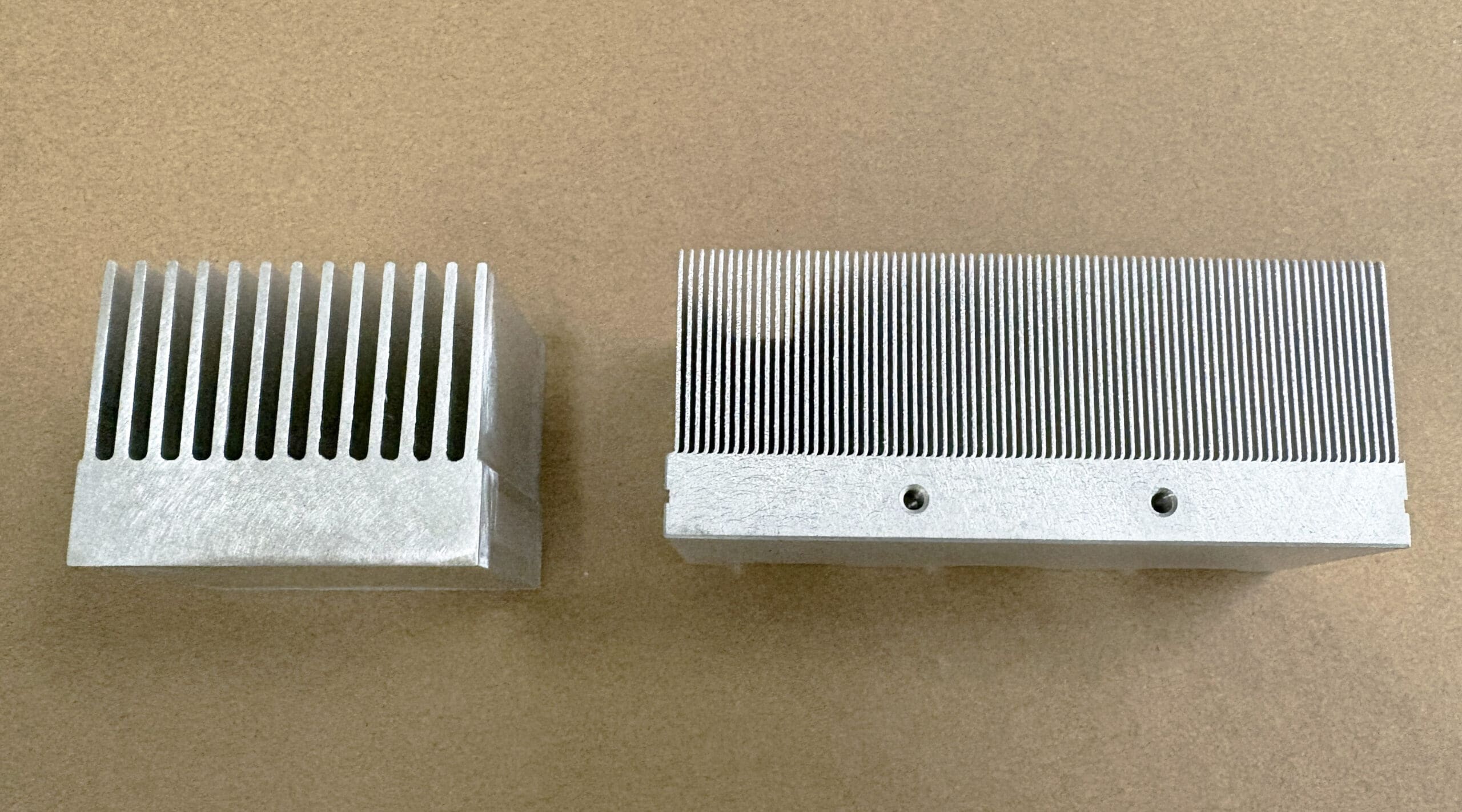
Skived heat sinks can produce thin fins with much tighter spacing than many conventional extrusion profiles.
The fins are formed directly from the base material, so aluminum and copper skived heat sinks can achieve high fin densities without requiring an extrusion die.
This makes skiving useful for compact forced-air designs where the available envelope requires more fin surface.
But high fin density is only an advantage when the airflow can use it.
A skived heat sink with extremely narrow channels can still perform poorly if the fan or system cannot provide sufficient airflow through those channels.
Skiving expands the manufacturable fin-density range; it does not remove the need to optimize airflow.
Bonded Fin Heat Sinks
For very large heat sinks, tall fin structures, or assemblies that exceed practical extrusion dimensions, a bonded fin heat sink may provide another option.
Because the fins and base are manufactured separately and then joined, bonded-fin construction provides flexibility in fin height, spacing, base dimensions, and material combinations.
The appropriate process should therefore be selected after considering both the thermal geometry and production requirements.
What Engineers Should Define Before Finalizing the Fin Gap
A heat sink manufacturer can provide more useful DFM feedback when the fin spacing is evaluated in the context of the complete application.
Before locking the geometry, it is useful to define:
- Heat load
- Available heat sink envelope
- Natural or forced convection
- Airflow direction
- Fin length in the airflow direction
- Fan or blower information
- Enclosure restrictions
- Ambient conditions
- Material
- Mounting requirements
- Expected production quantity
For forced-air systems, a fan curve is more useful than a free-air CFM number alone.
For passive systems, orientation and available clearance around the heat sink are particularly important.
And for manufacturing, the expected quantity matters because a custom extrusion die may make sense for repeat production, while skiving can sometimes provide more design flexibility without dedicated extrusion tooling.
A Manufacturing Note From XINXIANG
From a manufacturing perspective, we recommend avoiding extremely narrow fin gaps simply because they appear to provide more cooling area.
For a custom extruded heat sink, relatively small changes to fin thickness, height, or spacing can make the profile easier to extrude and may simplify tooling without significantly changing the available cooling envelope.
When the required geometry goes beyond practical extrusion limits, skiving or bonded-fin construction can be evaluated instead.
XINXIANG manufactures extruded, skived, and bonded-fin heat sinks and can review the fin geometry together with material, airflow, machining requirements, quantity, and target cost before production.
The objective is not to manufacture the greatest possible number of fins.
It is to manufacture a fin structure that makes sense for the thermal system and the production process at the same time.
Conclusion
Heat sink fin spacing is a system-level design decision.
More fins increase nominal surface area, but closer spacing can restrict natural convection or increase pressure drop under forced airflow. Fin length, orientation, fan capability, enclosure resistance, and manufacturing method all influence where the useful balance lies.
For passive cooling, sufficient channel space must remain for buoyancy-driven airflow.
For forced-air cooling, the heat sink should be evaluated together with the fan’s pressure-flow characteristics and the resistance of the complete airflow path.
And from a manufacturing standpoint, the required fin geometry should help determine whether extrusion, skiving, or bonded-fin construction is the most practical process.
Instead of asking:
“How many fins can we fit?”
ask:
“What fin spacing gives the available airflow enough effective surface area—and can that geometry be manufactured economically?”
Need Help With a Custom Heat Sink?
If you are developing a new heat sink, send XINXIANG your drawing or available envelope together with the heat load, airflow conditions, material, quantity, and manufacturing requirements.
We can review whether an existing extrusion, custom extrusion, skived heat sink, bonded-fin structure, or another manufacturing approach is a practical fit for your project.
