A pin-fin heat sink may look more sophisticated than a conventional straight-fin extrusion, but a larger number of exposed surfaces does not automatically mean better cooling. In an electronic enclosure, the air must actually reach those surfaces, carry heat away, and pass through the heat sink without exceeding the available fan pressure.
For engineers selecting a custom heat sink, the useful comparison is not simply pins versus plates. It is how each geometry behaves under the equipment’s real airflow, available space, temperature limit, and manufacturing requirements.
This guide compares pin-fin and plate-fin heat sinks for natural and forced convection, explains the trade-off between thermal performance and pressure drop, and connects those design choices to practical manufacturing processes.
From a manufacturing perspective, the challenge is to choose a fin geometry that meets the application requirements while remaining practical to produce, machine, inspect, and purchase at the required quantity.
What Is the Difference Between Pin Fins and Plate Fins?
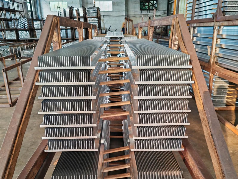
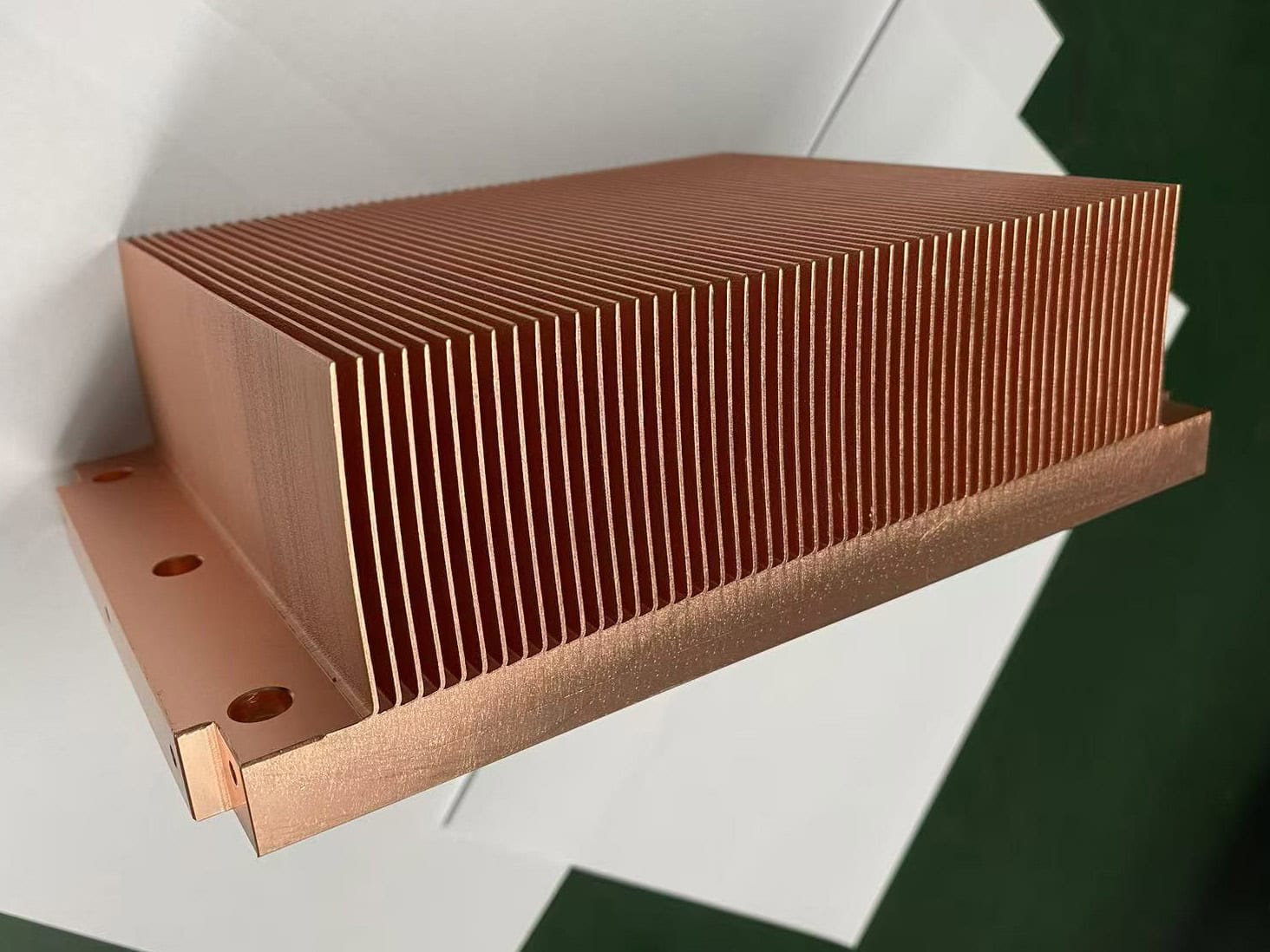
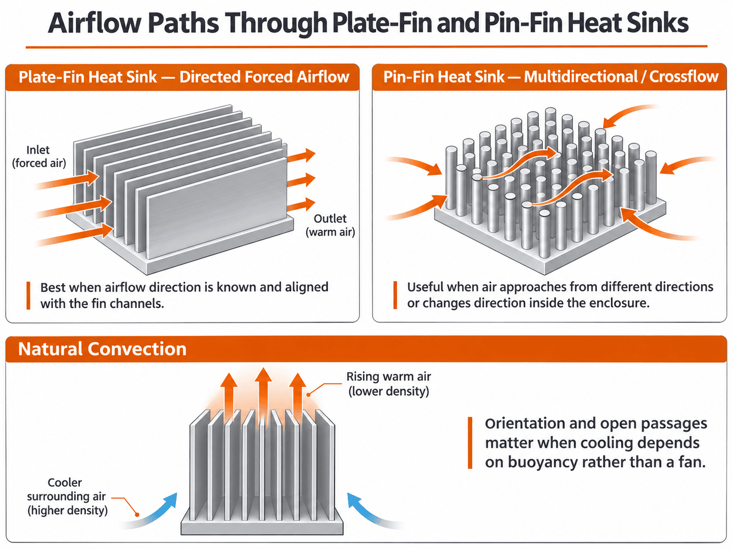
Plate-fin heat sinks use continuous, usually parallel fins projecting from a base. The spaces between them form defined channels. When air approaches along those channels, flow can be guided from inlet to outlet with relatively little unnecessary obstruction. Plate fins may be straight, tapered, flared, or otherwise optimized.
Pin-fin heat sinks use separate posts distributed across a base. Pins may be round, square, elliptical, or another manufacturable cross-section, and can be arranged in inline or staggered arrays. Air can move between pins from more than one lateral direction, but the exact flow resistance and heat transfer still depend on pin shape, pitch, height, and surrounding duct geometry.
Do not confuse radial fins with pin fins: a round heat sink may have continuous fins radiating outward from a center rather than an array of individual pins. The two geometries have different flow paths and manufacturing options; see our round heat sink overview for that distinction.
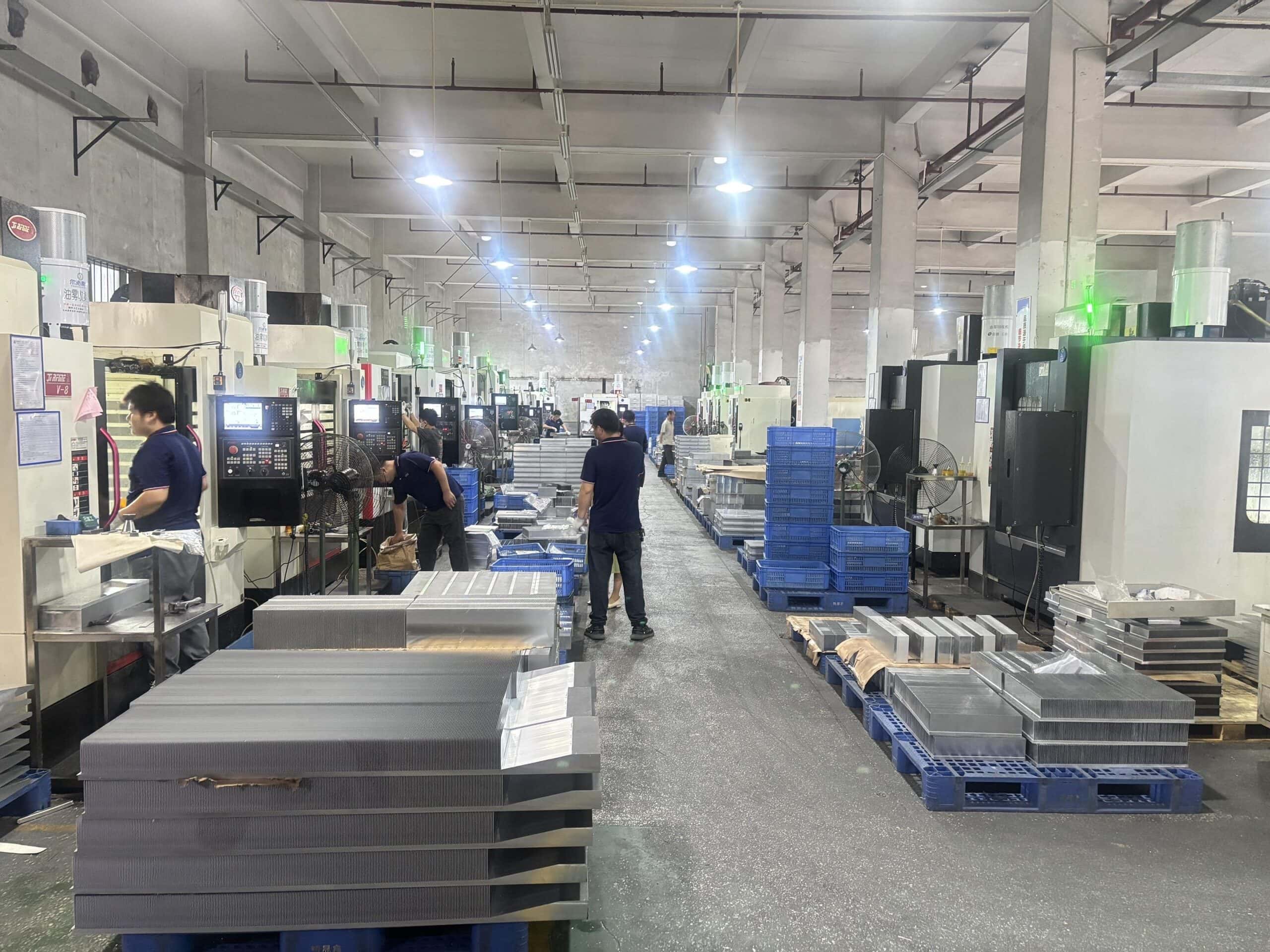
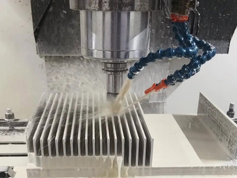
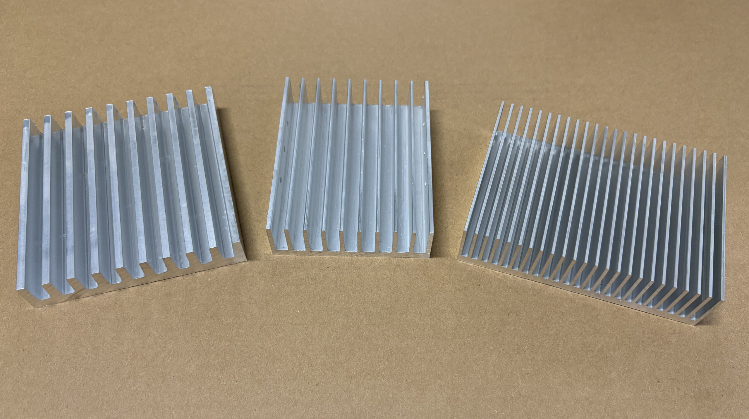
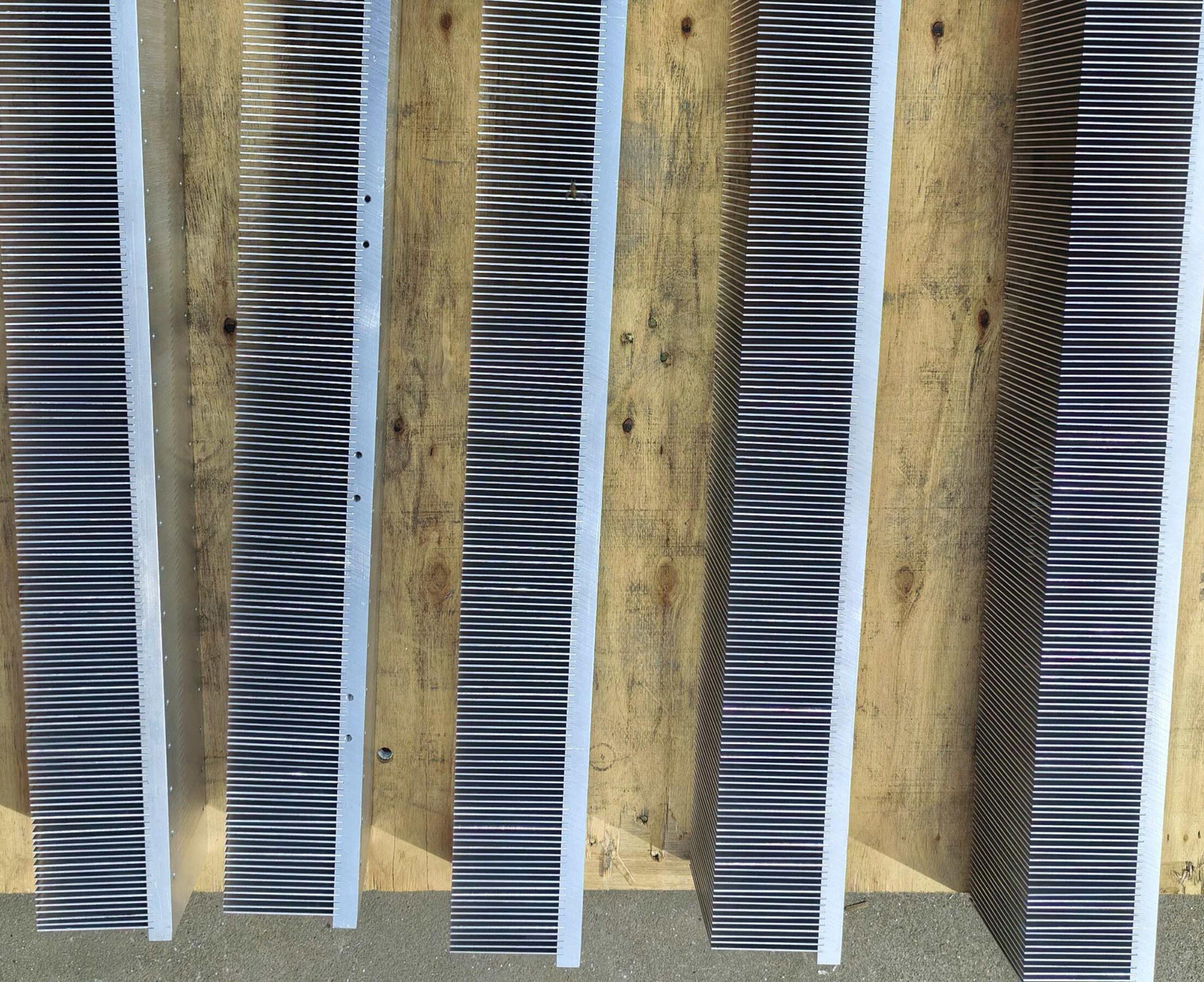
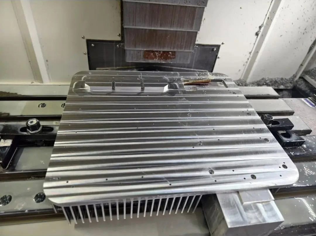
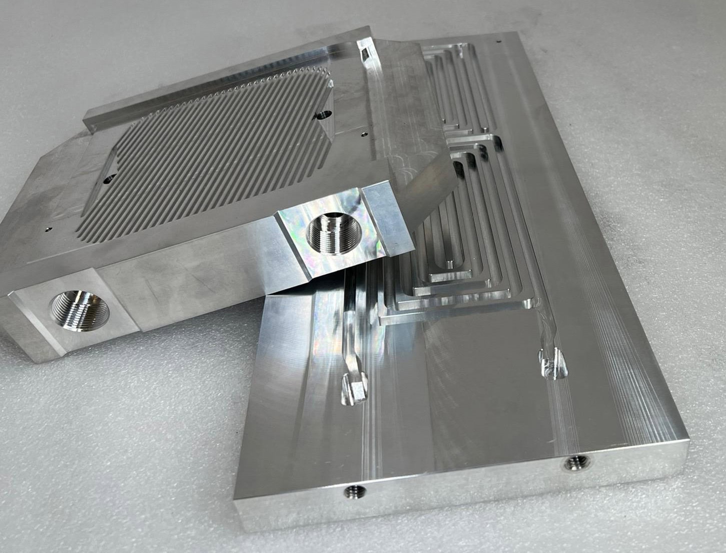
The product photographs below illustrate fin structures, not a controlled comparison of thermal performance.


Airflow Direction: The First Design Question
Forced airflow through straight channels
When a fan or blower pushes air in a known direction, an aligned plate-fin heat sink is often a sensible starting point. Air can enter between the plates, travel along the channels, and leave the opposite side. If the airflow path is controlled by a duct, plate-fin geometry can offer an effective balance of heat-transfer area and flow resistance.
However, an extrusion with very dense fins is not automatically efficient. Narrow channels can restrict airflow, especially when a small axial fan is working against other enclosure losses. A plate-fin design should be assessed using the airflow that will actually pass through it—not the fan’s free-air rating.
Crossflow, turning flow, and air approaching from several directions
A pin array can be useful when air approaches laterally from different directions or changes direction around neighboring components. Unlike continuous plates, individual pins do not create a single long, uninterrupted channel orientation. That geometric flexibility can help in compact enclosures with uncertain or distributed airflow.
But pin fins are not direction-independent in every practical system. A staggered array behaves differently from an inline array, and the fan position, inlet opening, bypass paths, and pin-to-pin spacing can alter the flow field significantly. The array may also create more resistance than a well-aligned straight-fin design.
Natural convection and mounting orientation
Without a fan, warmer air rises through buoyancy. Fin orientation, open passages, the direction of gravity, and available clearance can be as important as nominal surface area. Vertical plate-fin channels often provide a straightforward upward flow path; pin arrays may accommodate alternative arrangements, but must still permit sufficient air circulation.
A published comparison of optimized plate-fin and pin-fin heat sinks with vertically oriented base plates found that plate fins delivered greater total heat dissipation in many of the studied practical conditions, whereas pin fins often performed better when heat dissipation was normalized by mass. These are results for the specific optimization conditions—not proof that either fin type always wins in natural convection.
Thermal Resistance and Pressure Drop Must Be Evaluated Together
The purpose of both geometries is to provide a low-resistance path for heat to move from the device to surrounding air. A useful first check for an air-cooled heat sink is its required sink-to-air thermal resistance:
Rθsa,target = (Tbase,max − Tair,inlet) / Q
Here, Q is the heat transferred through the heat sink in watts, Tbase,max is the allowed heat sink base temperature, and Tair,inlet is the air temperature entering the heat sink. For example, if the heat sink must reject 90 W, inlet air is 40 °C, and the allowed base temperature is 85 °C, the preliminary target is 0.50 °C/W. This is a sizing illustration, not a tested result for a particular product.
It is also not the complete semiconductor thermal budget. When the limit is specified as junction temperature, the junction-to-case path, mounting interface, thermal interface material, base spreading resistance, and possible nonuniform heating must be considered separately.
More fins or pins can increase the available surface area and improve convection, but they also occupy space that air must pass through. With forced airflow, a restrictive design increases pressure drop. The intersection of the fan performance curve and the system resistance curve determines the real operating flow rate; an apparent gain at a fixed test velocity may disappear if the installed fan cannot deliver that velocity.
For more on how fin pitch and channel spacing affect usable surface area and airflow resistance, see our heat sink fin spacing guide.
This is why fair comparisons should state the boundary condition. Are two heat sinks being compared at the same external dimensions, the same airflow rate, the same fan speed, the same allowable pressure drop, or the same fan pumping power? Different conditions can produce different winners.
Experimental and analytical work on parallel forced flow has shown that optimized plate fins can be preferable at relatively low pumping power and longer flow lengths, while optimized pin fins can be advantageous at higher pumping power and shorter flow lengths. The result reinforces a practical rule: compare thermal resistance and air-side pressure drop as a pair.
Manufacturing Options: Geometry, Volume, and Cost
Fin layout affects which manufacturing processes are realistic. For a custom component, the best-performing concept on a drawing must also be producible at the required quality, quantity, and price.
| Manufacturing route | Geometry it commonly suits | Practical trade-off |
|---|---|---|
| Aluminum extrusion | Continuous straight or shaped plate-fin profiles with a constant cross-section | Existing profiles can reduce tooling investment and lead time; extrusion has design limits on fin thickness, gap, and aspect ratio. Cut-to-length and CNC features may still be required. |
| Cold forging | Integrated pin arrays and certain compact fin structures | Can produce a one-piece base and pins, particularly for production quantities; pin slenderness, die design, material formability, and tooling cost must be reviewed. |
| Skiving | Thin, closely spaced plate fins formed from aluminum or copper stock | Creates one-piece fins and base without an added bonding interface; geometry, blade access, fin height, and process limits determine feasibility. It is not normally the first choice for a conventional discrete pin array. |
| Die casting or CNC machining | Cast: integrated, more complex three-dimensional features; CNC: low-volume prototypes or difficult local details | Die casting requires tooling and material/porosity review; fully machining dense fins or pins can be expensive and time-consuming. Some parts combine primary forming with secondary CNC. |
For conventional extruded heat sinks, using an existing extrusion profile can be a particularly attractive starting point when the plate-fin arrangement and available envelope are compatible. A custom die is justified when the geometry or production requirement demands it. By contrast, a compact pin-fin concept may lead to a forged heat sink design review. If very thin continuous fins are needed, skiving may deserve consideration.
Material grade, base thickness, mounting features, tolerances, finish, annual volume, and inspection requirements all influence the final production cost. A geometry should be checked for manufacturing feasibility before tooling or a prototype is committed.
How XINXIANG Reviews Pin-Fin and Plate-Fin Designs
At XINXIANG, a manufacturing review starts with the customer’s drawing, available envelope, mounting features, airflow information, and expected production quantity. Rather than selecting a process from the fin count alone, we compare practical ways to produce the required geometry and finish the complete component.
For a straight plate-fin concept, we first consider whether a suitable section is already available in our heat sink extrusion profile library. Existing tooling can reduce the initial die investment; cutting to length, base machining, drilling, and tapping may then create the finished part. If an existing section requires excessive material removal or does not match the thermal and mechanical envelope, a new extrusion die may be more economical for repeat production.
For an array of individual pins, cold forging or another process may be worth evaluating, depending on pin geometry, die access, alloy, and production volume. If a design calls for extremely thin, closely spaced continuous plates, skiving offers a different route. We also consider how the chosen structure will affect handling, secondary CNC work, inspection, and part-to-part consistency.
Our manufacturing assessment is not a substitute for system-level thermal validation. The final design should be checked at the intended airflow, mounting orientation, ambient conditions, and heat load.
Which Geometry Makes Sense for Different Applications?
Application labels alone do not determine the fin type. The following are starting points for engineering review, not universal recommendations:
| Application condition | Reasonable starting point | What to verify |
|---|---|---|
| Ducted industrial power electronics with one established inlet-to-outlet flow path | Aligned plate fins | Actual fan flow, channel pressure drop, hotspot position, and mounting-interface temperature. |
| Compact electronics with crossflow or air arriving around components | Pin-fin array | Flow bypass, obstruction, array pitch, weight, manufacturability, and acoustic impact. |
| Fanless equipment with a vertical installation orientation | Vertical plate fins or a well-ventilated pin array | Natural-convection clearance, fin orientation, ambient temperature, enclosure openings, and radiation contribution. |
| Low-height assembly with a blower or impinging fan | Either, depending on impingement and exhaust paths | How air leaves the heat sink, available fan pressure, thermal contact, and operating-point testing. |
| Long, repeatable profiles across multiple product lengths | Plate-fin extrusion | Cross-section availability, cutting and machining requirements, tooling economics, and production volume. |
For outdoor or fanless equipment, be especially careful about dust, debris, water exposure, and the possibility that the installation orientation will differ from the lab setup. For fan-cooled assemblies, evaluate the fins together with the fan and enclosure; our active heat sink page explains the role of the complete cooling assembly.
A Practical Checklist Before Requesting a Custom Heat Sink
Whether you are considering pins or plates, sending the following information to the manufacturer will make a design review more productive:
- Heat source: component type, approximate power loss, hotspot locations, and maximum permitted temperature.
- Available envelope: maximum width, length, height, mass target, and the space reserved for airflow.
- Cooling method: natural convection, axial fan, blower, impingement, or ducted airflow; include the fan curve where available.
- Installation: mounting orientation, enclosure openings, nearby obstructions, and expected ambient temperature range.
- Mechanical interface: base flatness, mounting holes, fasteners, TIM, and any electrical isolation requirements.
- Manufacturing constraints: material preference, surface finish, prototype quantity, annual volume, and target cost.
- Validation: whether the design requires CFD, a thermal-resistance curve, or prototype testing in the final assembly.
Early on, it is often more productive to compare two manufacturable concepts under the same realistic operating conditions than to optimize an idealized fin array in isolation. A high surface-area design that blocks the available airflow, requires uneconomical tooling, or cannot meet the mounting tolerances is not a better practical solution.
Choose the Air Path First, Then the Fin Geometry
Plate fins are an excellent candidate when the flow direction is known and channels can be aligned with it. Pin fins merit consideration when air approaches from multiple directions, compact packaging creates complex flow, or performance per unit mass is an important design target. Neither geometry has a universal thermal advantage.
Need Help Selecting a Manufacturable Heat Sink Design?
Send XINXIANG your 2D drawing or 3D CAD model, heat load, airflow conditions, available dimensions, and estimated production quantity. We can review suitable fin structures, material options, existing extrusion tooling, CNC machining requirements, and manufacturing feasibility for your project. Thermal performance should be verified under the actual operating conditions.
Technical References
The resources below support the general heat-transfer and fan-system principles discussed here. Their results apply to the stated test or model conditions and should not be taken as certified performance figures for any XINXIANG product.
- Joo and Kim, “Comparison of thermal performance between plate-fin and pin-fin heat sinks in natural convection,” International Journal of Heat and Mass Transfer (2015). DOI: 10.1016/j.ijheatmasstransfer.2014.12.023.
- S. J. Kim, D.-K. Kim, and H. H. Oh, “Comparison of Fluid Flow and Thermal Characteristics of Plate-Fin and Pin-Fin Heat Sinks Subject to a Parallel Flow,” Heat Transfer Engineering, 29(2), 169–177 (2008). DOI: 10.1080/01457630701686669.
- Wilcoxon and Martin, “Fan Cooling – Part 1: Determining Flow Rate,” Electronics Cooling (2022). Read the technical article.