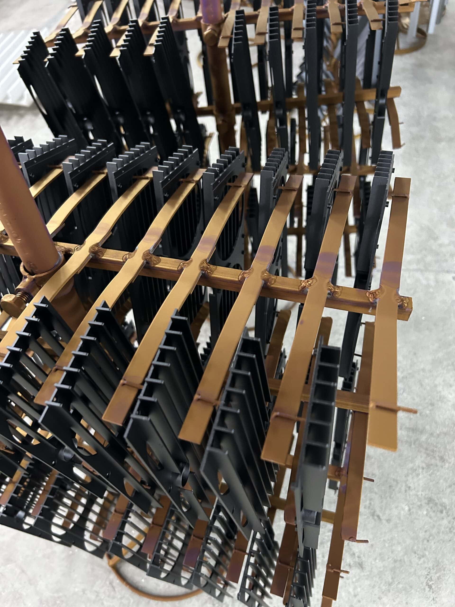
Choosing a liquid cold plate is not simply a matter of selecting an aluminum plate with coolant channels inside.
Two cold plates with similar outside dimensions can have very different thermal performance, pressure drop, manufacturing cost, and long-term reliability.
The difference often comes from how the coolant passages are formed, how the plate transfers heat into the fluid, how the components are joined, and how the finished assembly is inspected and tested.
Common liquid cold plate constructions include embedded-tube designs, CNC-machined flow channels, and brazed assemblies with internal fins or other heat-transfer features.
Each approach offers different advantages. The right choice depends on the heat-source layout, allowable component temperature, coolant conditions, mechanical requirements, operating pressure, production quantity, and total project cost.
In this guide, we compare the main liquid cold plate manufacturing methods and explain how engineers and buyers can select a practical construction for their projects.
If you are looking for a manufacturer rather than a technical comparison, explore our custom liquid cold plate manufacturing capabilities.
Start With the Cooling Requirements, Not the Manufacturing Process
Before deciding how a cold plate should be manufactured, the thermal and hydraulic requirements need to be understood.
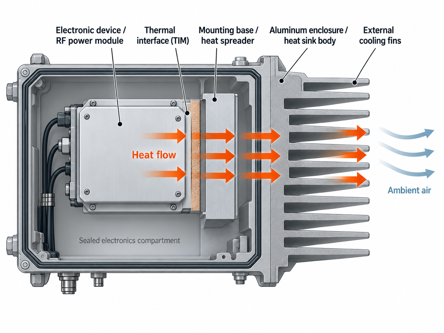
A liquid cold plate transfers heat from a component through a metal base and into circulating coolant. The coolant then carries that heat to a separate heat exchanger, radiator, or chiller.
For many applications, the simplified heat path is:
Heat source → Thermal interface → Cold plate base → Coolant passage wall or internal fins → Coolant
The overall cooling performance depends on several factors working together.
- Heat load: The total power that must be removed under continuous and peak operating conditions.
- Heat-source distribution: The size, number, and location of components mounted on the plate.
- Temperature limits: The maximum allowable component or mounting-surface temperature.
- Coolant inlet temperature: The temperature of the fluid entering the cold plate.
- Available flow rate: The coolant flow that the complete cooling system can actually deliver.
- Allowable pressure drop: The hydraulic resistance that can be accommodated within the system’s pump and flow requirements.
- Operating pressure: The normal and maximum pressures that the structure, ports, and seals must withstand.
- Mechanical envelope: Available length, width, thickness, mounting features, and connector positions.
These parameters should be defined before choosing a tube-in-plate, machined-channel, or brazed construction.
For example, a large plate with several moderately loaded components may benefit from a relatively simple coolant path. A compact plate with highly concentrated heat sources may need channels or internal heat-transfer features placed much closer to those components.
However, higher internal heat-transfer area is not automatically better. The design must also remain compatible with the available coolant flow, pressure-drop limit, cleanliness requirements, and manufacturing process.
For IGBT modules, inverters, converters, and other high-power applications, cold plate selection should also consider the module-to-base thermal interface and heat-source distribution. Learn more about our power electronics thermal solutions.
1. Embedded-Tube Cold Plates: A Practical Starting Point
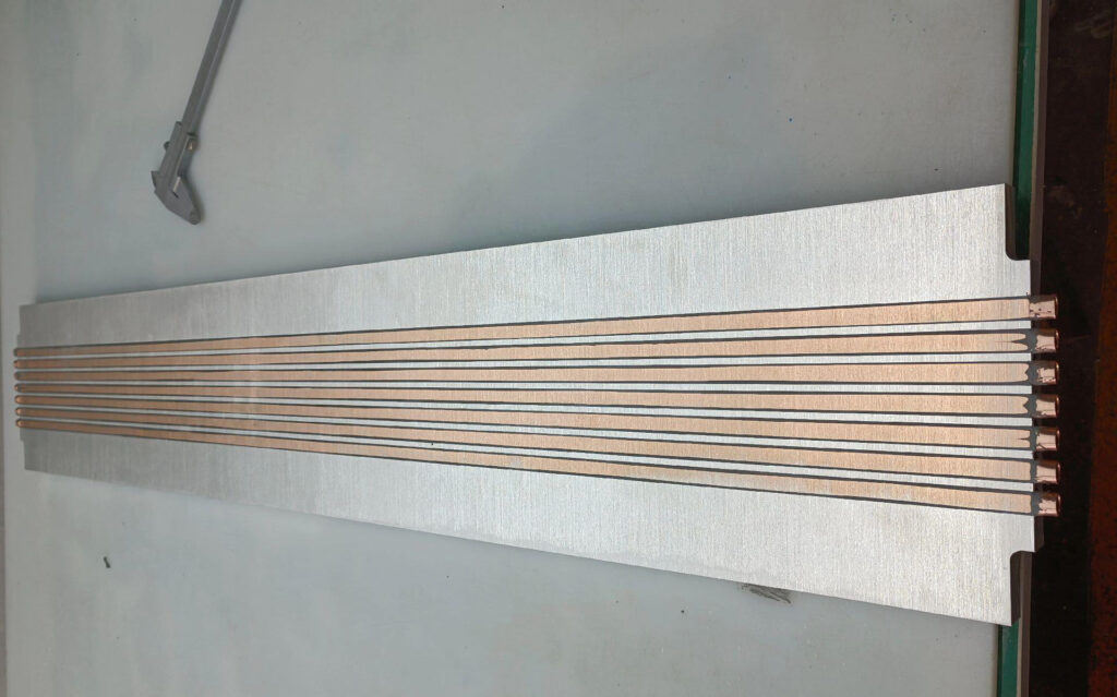
Embedded-tube cold plates, also called tube-in-plate cold plates, use metal tubing installed into grooves or channels in a larger base plate.
The base is commonly aluminum, while the embedded tubing may be copper, stainless steel, or another material selected for the coolant and operating conditions.
The coolant flows through the tubing, while heat from the electronic components travels through the base and into the tube wall.
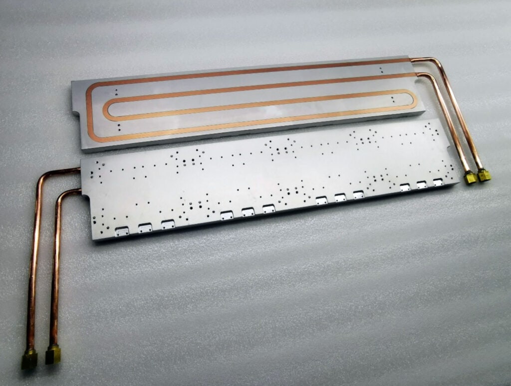
How Embedded-Tube Cold Plates Are Manufactured
A typical manufacturing process includes machining or forming grooves in the base plate, preparing the tubing to the required shape, installing it into the grooves, and securing it using an appropriate joining or retention method.
Depending on the design, the tube may be mechanically pressed into the groove, bonded, soldered, or secured through another suitable process.
Additional CNC machining may be required to create mounting holes, pockets, component-contact surfaces, or other finished features.
The quality of the thermal contact between the tube and base is important. Poor contact or excessive bonding material can add thermal resistance between the heated plate and the coolant.
When Is Tube-in-Plate a Good Choice?
Embedded-tube construction is often worth considering when:
- The heat load is moderate relative to the available cooling area.
- The heat sources are distributed over a relatively large plate.
- A straightforward serpentine or multi-pass tube path is suitable.
- Initial tooling investment and manufacturing simplicity are important.
- The selected tube material is compatible with the cooling loop.
A potential advantage is that the coolant can remain contained within continuous tubing rather than flowing through a large internal cavity formed by two joined plates.
However, the tube connections and any additional joints must still be designed and tested for leakage.
The main thermal limitation is that coolant contact area is largely determined by the tubing geometry and its contact with the base. A simple embedded-tube structure may not provide sufficient local cooling for every high-heat-flux application.
For projects requiring greater heat-transfer area directly beneath concentrated heat sources, a machined-channel or internal-fin construction may be more suitable.
2. CNC-Machined-Channel Cold Plates: Greater Flow-Path Flexibility
CNC-machined cold plates use milling or other machining operations to create coolant passages directly in a metal body.
This provides considerable design flexibility because the channel shape, depth, width, routing, and location can be adjusted to match the heat-source arrangement and mechanical envelope.
Common channel layouts include serpentine paths, parallel channels, multi-pass arrangements, and more complex distribution structures.
After machining, an open channel normally requires a cover or another joining method to create a sealed coolant passage.
Why Machined Channels Are Useful
CNC machining can place coolant passages closer to critical mounting areas while also integrating mechanical features into the same component.
These may include:
- Custom coolant channel geometry
- Different channel depths or widths
- Inlet and outlet manifolds
- Threaded ports and fittings
- Precision component mounting surfaces
- Mounting holes, pockets, and clearances
- Sealing grooves and cover interfaces
This flexibility can be especially valuable for industrial power electronics, laser equipment, and other systems with concentrated or unevenly distributed heat sources.
However, increased geometric flexibility does not automatically mean lower manufacturing cost.
Deep channels, narrow passages, complicated tool paths, thin walls, and difficult clamping arrangements can increase machining time and production risk.
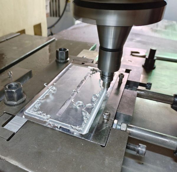
How Is the Channel Cover Sealed?
CNC machining describes how the channels are created. It does not, by itself, determine how the finished cold plate is sealed.
Common construction options include:
Brazed or welded cover: The channel body and cover are permanently joined using a process compatible with the materials and structural requirements. Suitable joining methods can provide a permanent metal assembly, but the joint design and process must be carefully controlled.
Mechanically fastened cover with a seal: A removable cover may be secured with screws or bolts and sealed using an O-ring or gasket. This can be useful for prototypes or serviceable designs, provided the groove geometry, clamping load, material compatibility, and operating conditions are properly evaluated.
Other specialized joining methods: Depending on the design, processes such as friction stir welding or other qualified joining techniques may be considered.
No joining process should be assumed suitable for every plate. Material grade, joint geometry, pressure requirements, cleanliness, and production quantity all influence the selection.
3. Brazed Cold Plates and Internal-Fin Constructions
Brazing is a joining process used to create a metallurgical connection between compatible components. It is not a separate coolant channel geometry.
For example, an aluminum cold plate may first be CNC-machined to create channels, assembled with a cover or internal fin structure, and then brazed to form the completed assembly.
Two common industrial approaches are vacuum brazing and controlled-atmosphere brazing (CAB). Their suitability depends on the materials, joint design, product geometry, production requirements, and qualified manufacturing process.
Why Use Internal Fins?
When the required heat-transfer area cannot be achieved with relatively simple passages, internal fins or other heat-transfer enhancements may be considered.
These structures increase the area in contact with the coolant and can influence the flow pattern inside the plate.
Possible internal structures include folded fins, machined fins, pin-fin arrays, and other project-specific features.
Internal fins can be particularly useful for concentrated heat loads or applications where the available cold plate thickness is limited.
However, closer fin spacing, longer flow paths, or highly restrictive features can also increase pressure drop and sensitivity to contamination.
The objective should therefore be to achieve sufficient heat transfer within the available hydraulic conditions, rather than simply maximizing internal fin density.
Manufacturing Considerations for Brazed Assemblies
Brazed cold plates can provide considerable design freedom, but the joining process introduces additional requirements.
Important considerations include:
- Compatibility between base materials and brazing filler materials
- Cleaning and surface preparation before joining
- Joint clearance and contact between components
- Alignment and fixturing during the thermal cycle
- Potential distortion of thin plates and precision features
- Internal cleanliness and removal of manufacturing residues
- Inspection of joints, coolant passages, and external interfaces
Critical mounting surfaces may require finishing operations after joining if the thermal cycle affects flatness or dimensions.
A successful brazed cold plate must meet the thermal and hydraulic requirements while also providing reliable joints and acceptable production consistency.
4. Other Cold Plate Construction Options
Embedded tubes and machined-channel assemblies are not the only available manufacturing routes.
For example, stamped-channel cold plates can be practical for repeat production when the required geometry is suitable for stamping and the tooling investment is justified.
Extruded multi-port tubes, drilled passages, manifolds, and other specialized constructions may also be considered.
The important distinction is between the flow-channel structure, the process used to form it, and the method used to join or seal the final assembly.
These choices work together rather than representing completely independent categories.
| Construction | Typical Best Fit | Main Advantages | Main Considerations |
|---|---|---|---|
| Embedded-Tube (Tube-in-Plate) | Distributed heat sources and relatively straightforward coolant paths | Simple construction, flexible cut and machining features, potentially lower initial cost | Tube-to-base thermal contact, tube routing, and available heat-transfer area |
| CNC-Machined Channels with Permanent Cover | Custom heat-source layouts and integrated mechanical features | Flexible channel geometry, localized cooling, and custom mounting interfaces | Machining time, wall thickness, joining quality, distortion, and leak integrity |
| CNC-Machined Channels with Sealed Removable Cover | Prototypes or designs requiring access to internal passages | Can permit disassembly, inspection, and design changes | Seal compatibility, fastener loading, groove accuracy, and long-term sealing reliability |
| Brazed Internal-Fin Construction | Compact designs requiring increased internal heat-transfer area | High internal surface area and integration of advanced flow structures | Pressure drop, material compatibility, brazing control, cleanliness, and inspection |
Flow-Channel Design: Balance Heat Transfer and Pressure Drop
The internal coolant path is one of the most important factors affecting cold plate performance.
Channel design determines how the liquid flows through the plate, how much heat-transfer area is available, and how evenly coolant reaches different heat sources.
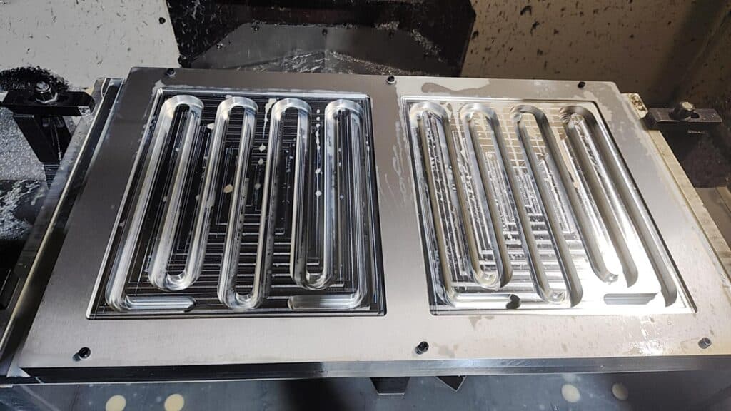
Serpentine Channels
A serpentine channel directs coolant through a continuous path across the cooling area.
This approach can simplify flow routing and ensure that the coolant passes through designated regions.
However, a long channel with several bends may create substantial pressure drop. The coolant also warms as it absorbs heat, so components near the downstream end may experience different thermal conditions from those near the inlet.
Parallel Channels
Parallel channels divide coolant flow among several branches.
They can reduce the flow resistance compared with a long, restrictive single passage, but the distribution manifolds must be designed carefully.
Uneven flow distribution can cause some regions to receive more coolant than others, potentially creating localized hot spots.
Microchannels and Enhanced Internal Surfaces
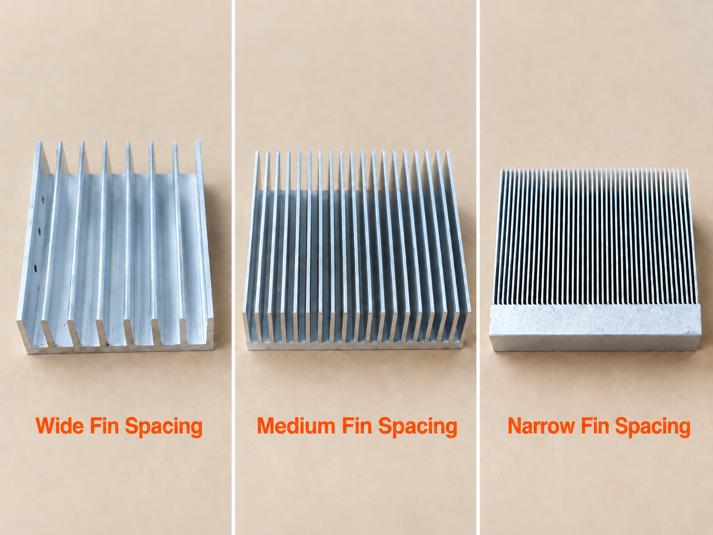
Smaller channels and closely spaced internal fins can increase the available solid-to-liquid heat-transfer area within a compact footprint.
However, very small passages can be more sensitive to particles, manufacturing variation, and flow restrictions.
For this reason, microchannel or high-density internal-fin designs should be evaluated together with coolant filtration, cleanliness, available pump pressure, and long-term maintenance requirements.
Why Pressure Drop Matters as Much as Thermal Performance
A cold plate should not be selected only by its thermal resistance or the temperature measured during a particular laboratory test.
Increasing flow rate can often improve convective heat transfer, but it also changes the pressure drop through the passages.
The complete liquid cooling loop includes additional flow resistance from hoses, fittings, manifolds, valves, filters, heat exchangers, and other components.
Therefore, the flow rate delivered by the actual pump may differ from the nominal value used to evaluate an individual cold plate.
Before finalizing a design, engineers should consider both the thermal performance and pressure drop at the intended operating flow rate.
Temperature measurements should also be compared under consistent conditions, including coolant inlet temperature, coolant composition, flow rate, heat-source location, and mounting interface.
Engineering Note: A lower cold plate thermal resistance measured at a higher coolant flow rate does not automatically make that design the better system choice. The required flow rate must be achievable within the complete cooling loop.
Select Materials Based on the Complete Cooling Loop
Aluminum and copper are common cold plate materials, but their suitability depends on more than thermal conductivity.
Aluminum Cold Plates
Aluminum offers a practical combination of thermal conductivity, relatively low weight, machinability, and material cost.
It is widely used for larger cold plates, integrated cooling structures, and applications where weight and production cost are important considerations.
Copper Cold Plates
Copper offers higher thermal conductivity and may provide improved local heat spreading when the heat source is concentrated within a small area.
However, copper is substantially heavier and generally more expensive than aluminum. Material selection should consider the actual thermal bottleneck rather than conductivity alone.
Our copper heat sink page provides more information about copper thermal components and manufacturing options.
Coolant and Wetted-Material Compatibility
The materials in contact with the coolant must be compatible with the working fluid and the other components in the cooling loop.
Possible coolants include suitably treated water, water-glycol mixtures, oils, and application-specific fluids.
The correct choice depends on operating temperature, corrosion protection, freezing conditions, fluid properties, seals, and overall system requirements.
Special attention is required when aluminum and copper are both exposed to the same conductive coolant. Without suitable corrosion control, galvanic corrosion can reduce reliability and damage the cooling system.
In an embedded copper-tube plate, the wetted surface may be the inside of the copper tubing rather than the surrounding aluminum base, provided the coolant path remains entirely within the tubing and its compatible connections.
The complete list of wetted metals, seals, fittings, hoses, and other fluid-contacting materials should therefore be reviewed before selecting the coolant.
Surface coatings or corrosion inhibitors should not be assumed to solve every material-compatibility problem without appropriate system validation.
Manufacturing Quality Is Critical to Cold Plate Reliability
Thermal performance is only one part of a successful cold plate design.
A production-ready liquid cold plate must also maintain the required mechanical dimensions, withstand the specified operating conditions, remain sufficiently clean internally, and provide reliable coolant containment throughout its service life.
Control Mounting Surfaces and Wall Thickness
Cold plates often interface with IGBT modules, semiconductor packages, laser assemblies, or other components that require controlled mounting surfaces.
Surface flatness, roughness, hole locations, and thermal interface requirements should follow the applicable component specifications or approved customer drawing.
Channel depth and base thickness must also leave adequate material for mechanical loads, threaded features, joining areas, and required pressure resistance.
Making the coolant wall thinner may shorten the thermal conduction path, but it can also reduce structural margin. The final thickness must satisfy both the thermal and mechanical requirements.
Plan the Joining Process Early
For cold plates with machined channels and a separate cover, the joining method should be considered before the detailed channel geometry is finalized.
The design must provide suitable joining surfaces, adequate access, manageable deformation, and a reliable seal around the coolant passages and fluid connections.
A geometry that is easy to machine is not necessarily easy to braze, weld, or assemble.
Reviewing the machining and joining processes together can reduce unnecessary redesign and manufacturing risk.
Internal Cleanliness Matters
Machining chips, burrs, particles, joining residues, and other contaminants can remain inside coolant passages if the manufacturing and cleaning processes are not properly controlled.
These contaminants can obstruct small passages, affect valves or pumps, increase flow resistance, and reduce heat-transfer performance.
Internal cleaning and inspection requirements are particularly important for narrow channels, internal-fin constructions, and other structures that are difficult to access after assembly.
Pressure Testing, Leak Testing, and Flow Verification
Cold plate testing should be defined according to the actual design requirements and the agreed inspection plan.
Different tests verify different aspects of the finished product.
Pressure testing evaluates whether the assembly can withstand specified pressure conditions without unacceptable deformation or failure.
Leak testing evaluates coolant containment at joints, covers, tubes, ports, and other potential leakage locations.
Flow verification checks whether the hydraulic behavior of the plate meets the required flow and pressure-drop conditions.
Thermal testing evaluates the cooling performance under defined heat loads, coolant temperatures, flow rates, and mounting conditions.
A pressure test alone should not be treated as proof of thermal performance. Similarly, a cold plate that achieves the target temperature in a laboratory still needs to meet the relevant structural and leak-tightness requirements.
Test pressure, method, duration, allowable leakage, sampling frequency, and acceptance criteria should be specified for the individual project.
For demanding applications, additional verification such as temperature cycling, vibration, corrosion, or other reliability testing may be required by the customer or applicable product specification.
Common Cold Plate Design and Manufacturing Mistakes
Choosing the construction before defining the heat load. A visually complex cooling structure may add cost without providing a meaningful advantage for the actual application.
Comparing thermal performance without matching test conditions. Different inlet temperatures, coolant types, flow rates, heat-source footprints, or interface conditions can make published performance figures difficult to compare.
Ignoring pressure drop. A highly restrictive internal channel may require more pump capability than the cooling system can provide.
Using incompatible materials in the coolant loop. The entire wetted-material system must be considered to reduce corrosion and long-term reliability risks.
Leaving joining and sealing decisions too late. Cover geometry, brazing surfaces, weld paths, or gasket grooves should influence the original mechanical design.
Applying unnecessarily tight tolerances everywhere. Critical mounting surfaces, ports, and sealing areas may need high precision, while non-functional areas can often use more practical manufacturing tolerances.
Overlooking internal cleaning. Burrs, machining chips, and joining residues can be particularly harmful in narrow or complex coolant passages.
Assuming one test verifies every requirement. Thermal performance, pressure resistance, leakage, flow behavior, and environmental reliability are different acceptance considerations.
How to Choose the Right Cold Plate Construction
A practical selection process should compare the thermal requirement, fluid system, manufacturing feasibility, and total cost rather than looking at manufacturing methods independently.
For example, an aluminum plate with distributed heat sources and a relatively simple coolant path may be a good candidate for embedded tubing.
If the heat sources are concentrated or the plate requires complicated mounting features, CNC-machined channels may offer more flexibility.
Where additional internal heat-transfer area is needed, a brazed structure with internal fins may be worth evaluating, provided the pressure drop and manufacturing requirements remain acceptable.
For early prototypes or serviceable assemblies, a mechanically sealed cover may also be considered when compatible with the operating pressure, fluid, and reliability requirements.
These are starting points, not fixed selection rules. Final construction should be supported by the project requirements and appropriate design review or testing.
What Information Is Needed for a Custom Cold Plate Quote?
Providing complete technical information helps the manufacturer evaluate the most suitable construction and prepare a more accurate quotation.
Useful project information includes:
- 2D drawings and 3D CAD models
- Overall plate dimensions and available thickness
- Heat-source locations and total heat load
- Maximum allowable component or mounting-surface temperature
- Coolant type and inlet temperature
- Required coolant flow rate
- Allowable pressure drop
- Normal and maximum operating pressure
- Inlet and outlet port types, locations, and orientation
- Mounting-surface flatness and other critical tolerances
- Material and surface treatment requirements
- Leak, pressure, flow, and other inspection requirements
- Prototype quantity and estimated annual production volume
If the internal flow path has not yet been finalized, the heat-source layout, coolant conditions, mounting requirements, and mechanical envelope are useful starting points for a manufacturing review.
For existing designs, a detailed drawing review can identify potential machining, joining, material, sealing, and inspection issues before production.
Conclusion: Select the Construction Around the Application
No single liquid cold plate manufacturing method is ideal for every cooling application.
Embedded-tube plates can provide a practical route for relatively straightforward cooling layouts. CNC-machined channels offer greater geometric flexibility, while brazed and internal-fin structures can be considered when the thermal and packaging requirements justify their additional complexity.
The best construction is not necessarily the most complicated one.
It is the design that meets the thermal requirement within the available coolant flow and pressure-drop limits while remaining reliable, manufacturable, and economical at the intended production volume.
Early consideration of materials, channel geometry, joining, machining, cleanliness, and testing can help reduce both engineering risk and production cost.
Need a Custom Liquid Cold Plate Manufacturer?
At XINXIANG, we manufacture custom liquid cold plates and thermal components for power electronics, industrial equipment, energy systems, and other demanding applications.
Our capabilities include CNC machining, embedded-tube constructions, precision mounting surfaces, fluid passage machining, component assembly, and project-specific manufacturing and joining solutions.
We review cold plate drawings according to the thermal requirements, coolant conditions, mechanical design, material selection, production quantity, and inspection requirements.
If you already have a completed design, send us your drawing and specifications for manufacturability review and quotation. If your project is still under development, we can evaluate practical construction options based on the information available.
Explore our custom liquid cold plate manufacturing services, or contact XINXIANG to discuss your cooling project.
Technical References
The following technical resources provide additional information on liquid cold plate constructions, thermal and hydraulic design, material compatibility, and qualification considerations:
Eaton / Boyd Thermal — Liquid Cold Plate Technologies and Manufacturing Methods
Boyd Corporation — Liquid Cooled Cold Plates Technical Data Sheet
Open Compute Project — Cold Plate Development and Qualification
Actual thermal performance, pressure capability, leak-tightness, coolant compatibility, and reliability requirements depend on the individual cold plate design and the specifications of the complete cooling system.