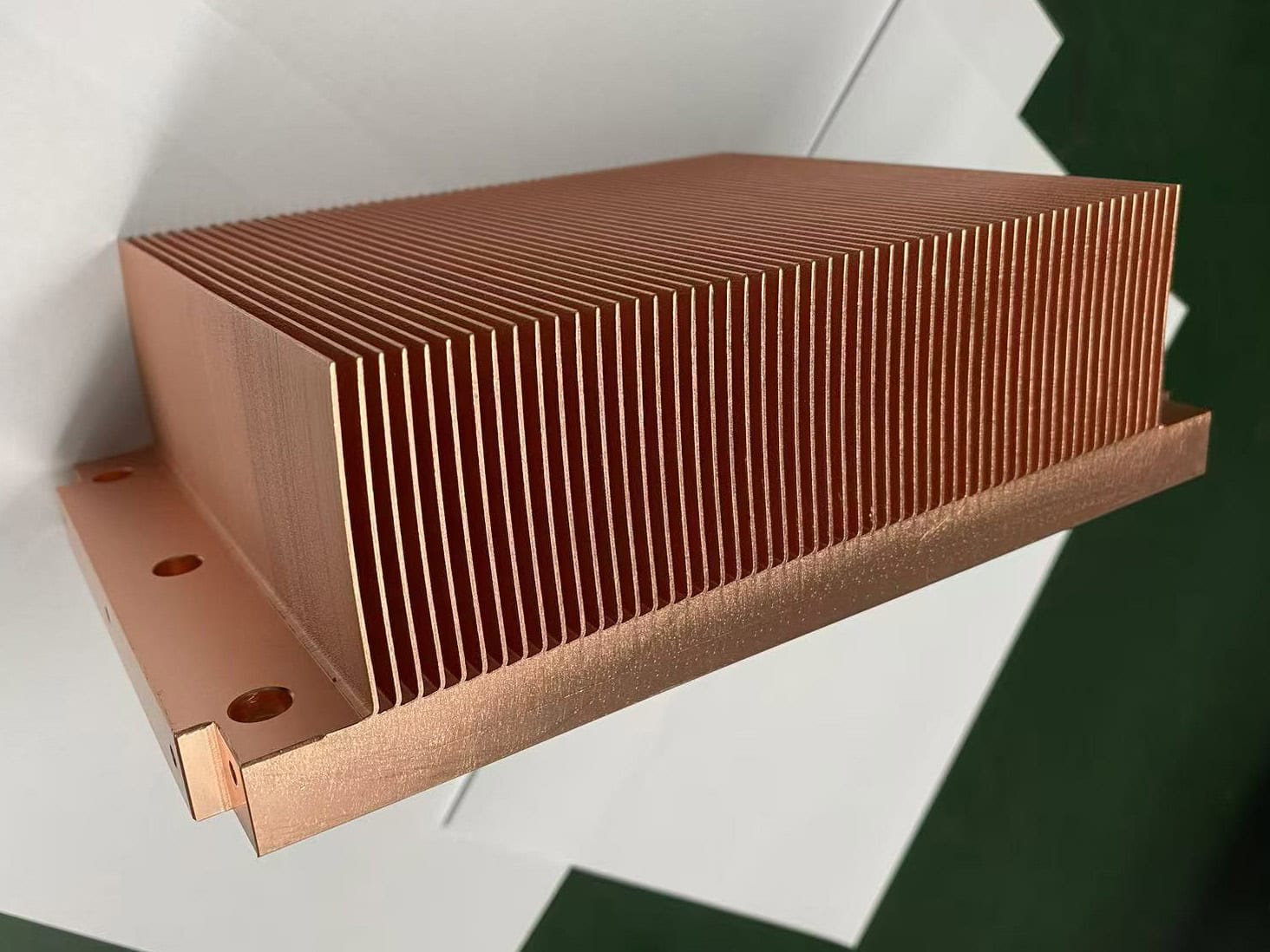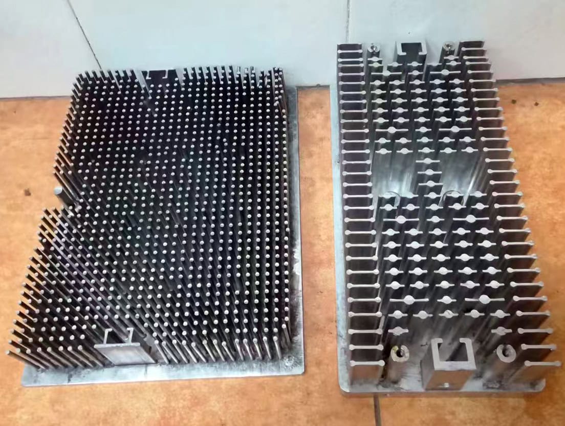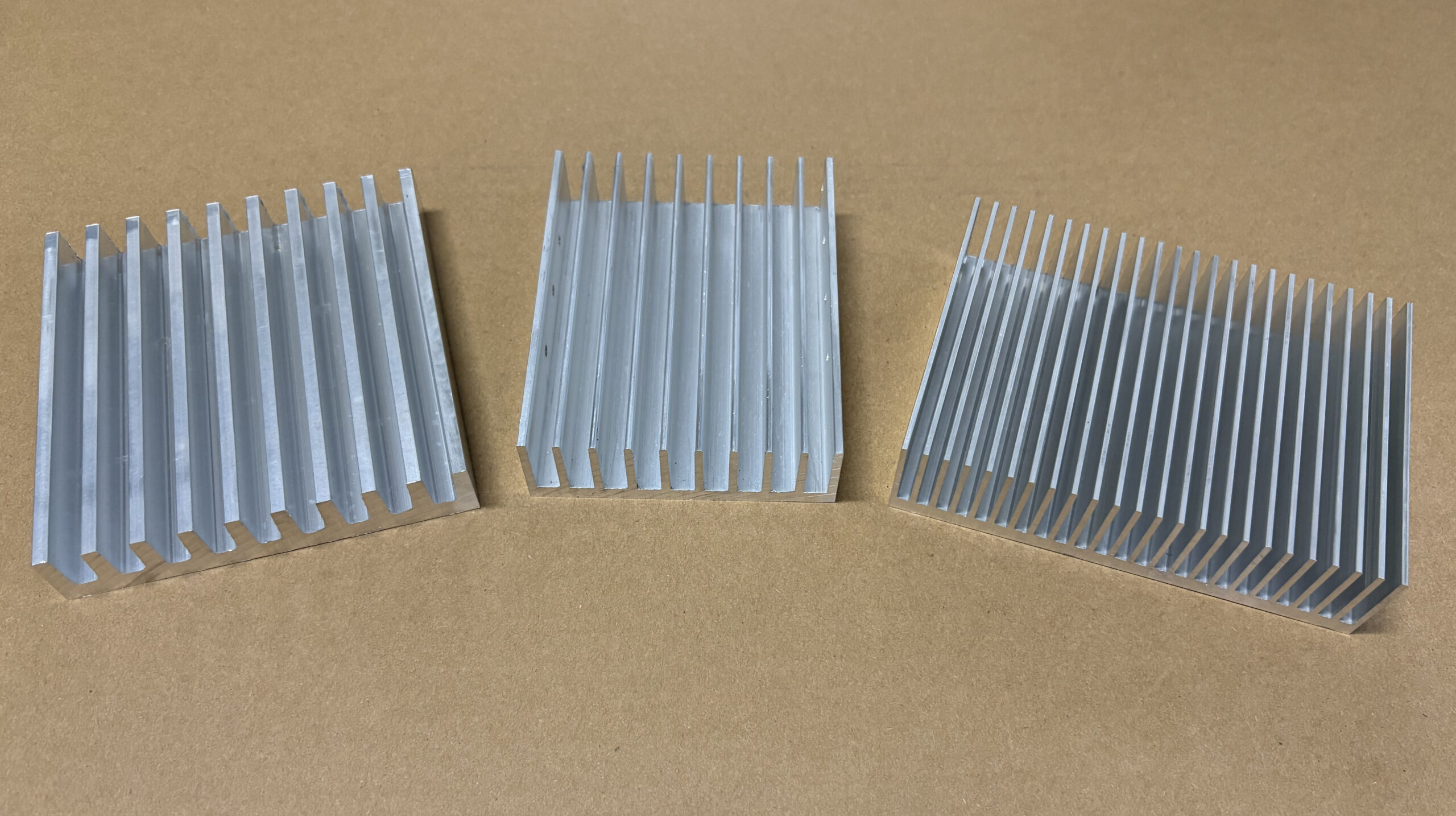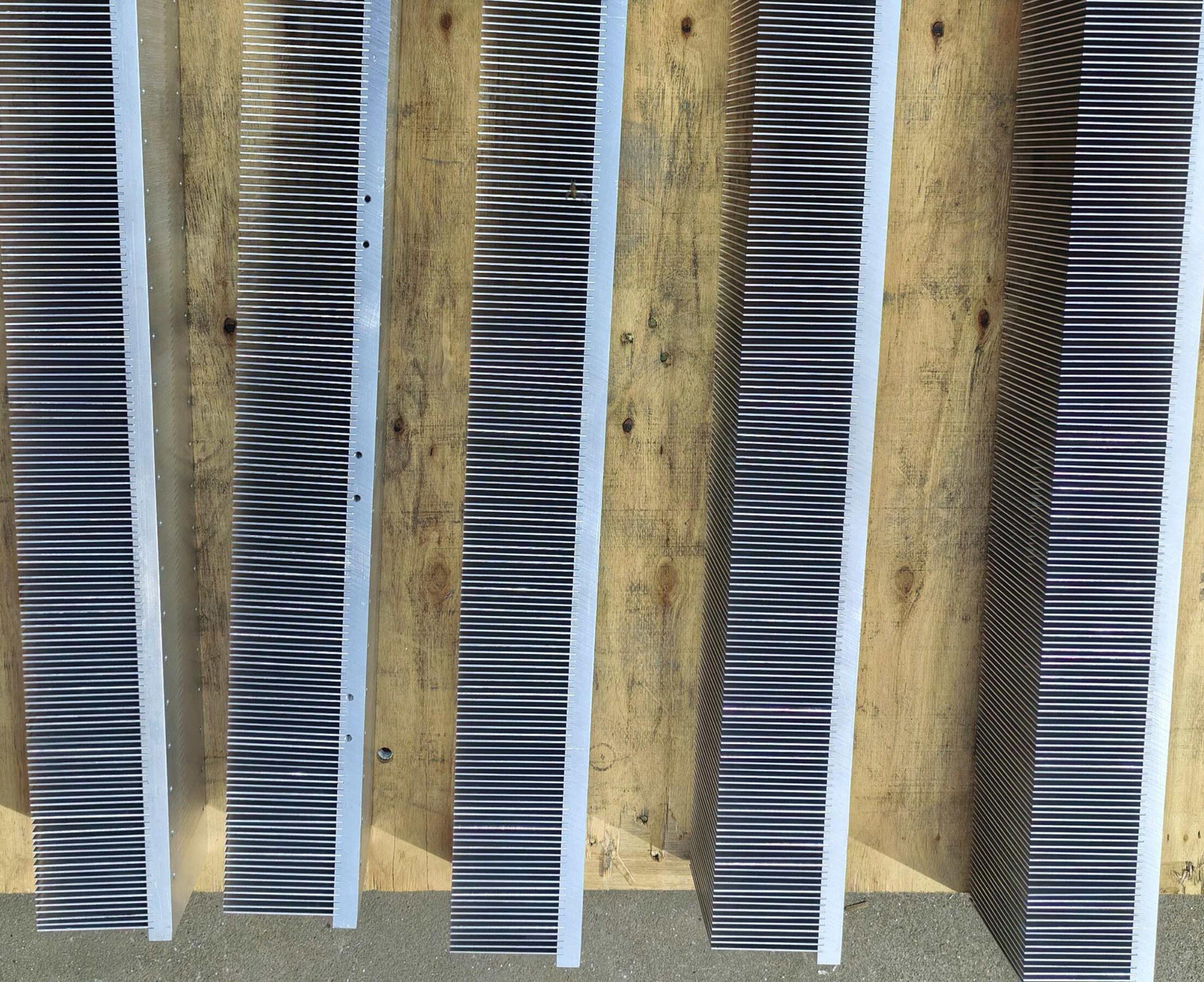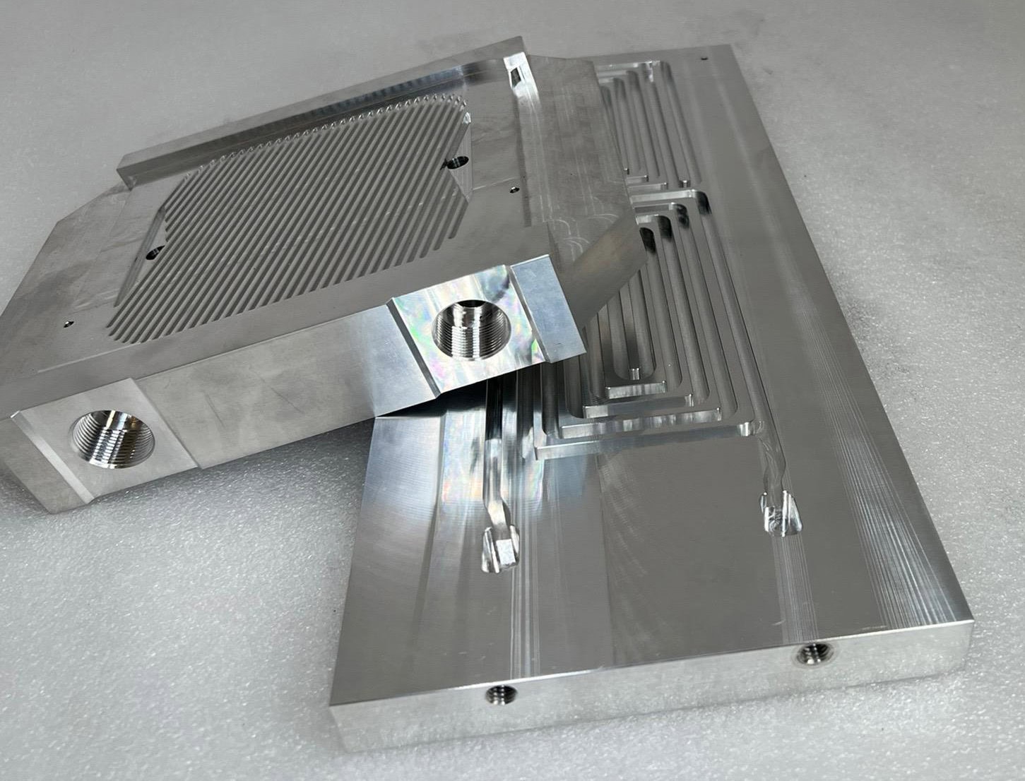
A heat sink can have a well-designed fin structure and still deliver disappointing cooling performance if its mounting surface does not make proper thermal contact with the heat source.
For power modules, IGBTs, and other high-power components, the interface between the device and the heat sink is part of the thermal path. Its performance depends not only on thermal interface material (TIM), but also on the shape and condition of the two mating surfaces.
Two drawing requirements are particularly important: base flatness and surface roughness. They are related, but they describe different characteristics—and making one more precise does not automatically improve the other.
For engineers and buyers specifying a custom heat sink, the objective is to define the mounting surface accurately enough for reliable assembly and heat transfer without adding machining and inspection costs where they are unnecessary.
Later in this guide, a real XINXIANG manufacturing case shows how a customer-specified 0.03 mm base-flatness tolerance influenced machining sequence, finishing, and final inspection for a large aluminum heat sink.


Why Heat Sink Base Flatness Matters
At a microscopic level, no machined metal surface is perfectly smooth. Even when two surfaces appear to touch, small gaps remain between their high points. Larger-scale bowing, twisting, or local steps can create additional separation across the mounting area.
Those gaps matter because trapped air conducts heat poorly compared with metal or an appropriately selected thermal interface material. A thermal grease, phase-change material, or pad can help accommodate surface irregularities, but its behavior depends on the material, pressure, and resulting bond-line thickness.
A significantly uneven heat sink base may produce an unnecessarily thick interface in some regions, inconsistent contact pressure, or mechanical stress on the mounted device. In high-power assemblies, these effects can contribute to higher or less predictable temperatures.
This is why mounting-surface quality should be reviewed alongside the heat sink’s fin geometry, airflow, and thermal resistance—not treated as a cosmetic detail.
Flatness vs. Surface Roughness: What Is the Difference?
Flatness describes the overall form of a surface. In geometric dimensioning and tolerancing (GD&T), a flatness tolerance controls a surface between two parallel planes separated by the specified tolerance value. It is a form control and does not require a datum reference.
For example, a flatness tolerance of 0.05 mm on a defined mounting face means that the controlled surface must fit within a pair of parallel planes 0.05 mm apart. It does not mean a ±0.05 mm thickness tolerance.
Surface roughness, by contrast, describes much smaller-scale texture, including the peaks and valleys left by machining or other manufacturing processes. Common profile parameters include:
- Ra: the arithmetic mean of the absolute profile deviations within the defined evaluation conditions.
- Rz: a profile height parameter describing peak-to-valley characteristics under the applicable measurement standard.
Ra and Rz are not interchangeable. The same Ra value can occur on surfaces with very different peak-and-valley shapes, and there is no universal conversion ratio that is appropriate for acceptance inspection. The applicable standard, measurement conditions, and parameter should be stated when they matter.
A surface can look smooth but still be warped. It can also be relatively flat overall while retaining noticeable tool marks. Both characteristics may need to be controlled, but they must be specified and inspected separately.

How Flat Does a Heat Sink Need to Be?
There is no universal flatness requirement for every heat sink. The correct specification depends on the component package, mounting-area dimensions, interface material, clamping arrangement, and the device manufacturer’s assembly instructions.
For example, Infineon’s assembly guidance provides different mounting-surface requirements for different power-module families:
| Manufacturer guidance | Flatness requirement | Roughness requirement | Scope and interpretation |
|---|---|---|---|
| Infineon Easy modules (AN2009-01, Rev. 1.1) | ≤ 50 µm over a 100 mm length | Rz ≤ 10 µm | Steps ≤ 10 µm; module and clamp mounting area. |
| Infineon 62 mm modules (AN2012-05) | ≤ 30 µm | Rz ≤ 10–15 µm | Contact area for the specified 62 mm module family. |
These examples illustrate module-specific recommendations, not general machining tolerances for all heat sinks. The exact value should be taken from the current documentation for the device being installed and interpreted according to its stated measurement area and conditions.
In particular, a manufacturer’s statement such as “flatness over 100 mm” should not be copied onto an unrelated drawing without identifying the controlled face and understanding the intended verification method.
For other applications, such as a small low-power electronic component mounted with a compliant thermal pad, the practical surface requirement may be different. Do not specify 0.03 mm or 0.05 mm simply because those values appear in an IGBT mounting guide.
Surface Roughness, Thermal Interface Material, and Contact Pressure
A rougher surface generally has more microscopic peaks and valleys, but the lowest possible Ra value is not automatically the best or most economical solution.
The thermal interface must be considered as a system. Its performance is affected by the roughness and shape of both contact surfaces, the selected TIM, application thickness, mounting pressure, and temperature cycling.
Thermal grease can fill small voids, while a compliant gap pad can accommodate certain larger variations. These materials are not direct substitutes: a pad with a relatively thick bond line may behave quite differently from a thin grease interface. The component and TIM suppliers’ application instructions should determine the selection and assembly process.
More material is not necessarily better. An unnecessarily thick interface can increase the conductive resistance of the TIM layer, even if it fills the gaps completely. Conversely, too little material or insufficient pressure can leave voids.
If the drawing specifies Ra 1.6 µm, for example, that callout should be treated as a surface-texture requirement—not as evidence that the base also meets a 0.05 mm flatness tolerance. Similarly, a drawing that requires Rz ≤ 10 µm cannot be verified merely by reporting an Ra reading.
The aim is a controlled, repeatable interface that matches the selected power component and assembly process.
When Is CNC Machining Necessary?
Many extruded heat sinks begin as continuous aluminum profiles that are cut to length and then machined where required. Extrusion offers economical fin geometry, but the as-extruded and cut surfaces should not automatically be assumed to satisfy a demanding module-mounting specification.
Face milling can produce a defined mounting plane and help control the interface surface. Other operations may include drilling, tapping, pockets, counterbores, and locating features for the device.
However, CNC machining is not mandatory for every heat sink. If a drawing allows the existing surface condition and the assembly performs adequately, machining a large base solely to improve appearance can waste time and material.
When a tighter requirement is necessary, manufacturers must consider more than the cutting tool. Results may be influenced by:
- The original extrusion’s straightness and residual stress.
- Base thickness and overall part stiffness.
- Clamping forces and how the part is supported during machining.
- Material removal, heat generation, and machining sequence.
- Burrs, scratches, handling damage, and distortion after unclamping.
- Later operations such as finishing or assembly.
A large thin-based heat sink can be particularly challenging because a surface that measures acceptably while restrained in a fixture may change shape after release. Where flatness is critical, the inspection condition should reflect the agreed drawing requirement rather than only the condition inside the machining fixture.
XINXIANG Manufacturing Case: Precision-Machined Heat Sink Base (0.03 mm Flatness)
For a large custom aluminum heat sink, the customer’s drawing specified a base flatness tolerance of 0.03 mm and required the finished mounting face to have no visible cutter-pass transition marks. Both the geometric tolerance and the surface appearance were important for this project.
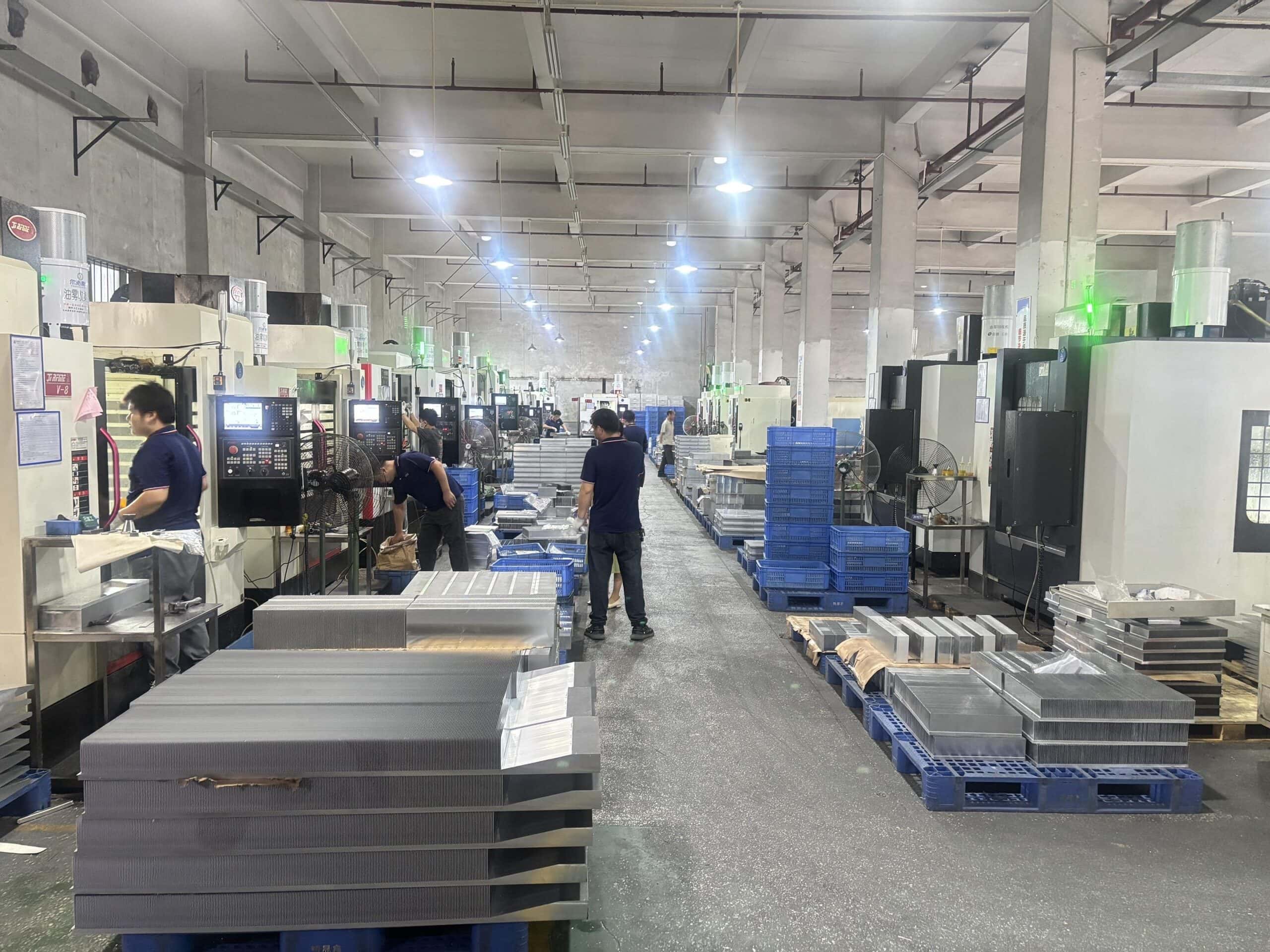
XINXIANG used a staged CNC machining process rather than attempting to achieve the final mounting-surface condition in a single operation. The following production photographs show the main stages, from machining and stabilization to inspection and the finished product.
Step 1 — Fin-Side CNC Machining
Machining on the fin side was performed first, before the final precision work on the mounting face. This sequence allowed the main structural features to be completed without treating the critical base surface as finished too early.

Step 2 — Rough Machining of the Base
The base was then rough-machined to remove most of the required material allowance. Machining a large aluminum part can redistribute residual stresses and contribute to dimensional movement, so roughing and finishing were scheduled as separate operations.

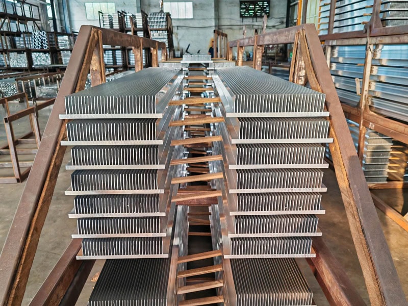
Step 3 — 24-Hour Stabilization After Rough Machining
After rough machining, the heat sinks were set aside for 24 hours before final finishing. This was a practical process-control interval to allow time for potential dimensional movement to become apparent. It was not a controlled stress-relief heat treatment and should not be interpreted as removing all residual stresses.

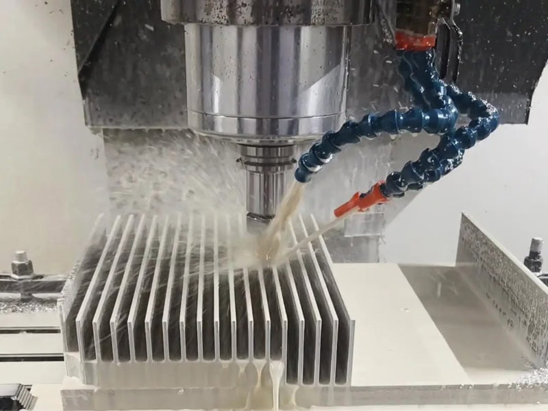
Step 4 — Final Precision Face Milling
The mounting face underwent a separate finish-machining operation. The objective was to meet the 0.03 mm flatness requirement while maintaining a consistent surface without visible transitions between cutter passes. Tool marks from ordinary machining texture are not the same as a step or mismatch at a pass boundary.

Step 5 — Final Inspection
After finishing, the heat sink was inspected against the customer’s drawing requirements. The final inspection was passed, including the specified 0.03 mm base flatness requirement. A clean-looking surface alone is not proof of flatness; compliance must be established by the agreed measurement and inspection process.
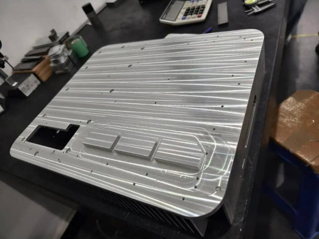
Step 6 — Finished Product
The completed heat sink combines a large finned structure with a precision-machined base mounting surface. The customer’s demanding flatness and surface-finish expectations shaped the machining sequence, not just the final cutting pass.

Manufacturing Takeaway
This project illustrates why a demanding mounting-face tolerance is a process-planning and inspection challenge, not merely a CNC machine specification. The sequence of fin-side machining, base roughing, a 24-hour stabilization period, separate precision finishing, and final inspection supported compliance with the customer’s requirements.
The 0.03 mm tolerance is specific to this project and should not be treated as a standard requirement for every heat sink. Flatness, surface texture, inspection conditions, and cost should be selected for each application.
What About Anodizing and Other Surface Finishes?
Anodizing is useful for corrosion resistance and appearance, but an anodized layer is not equivalent to bare machined aluminum. Coating thickness, electrical requirements, and the effect on the thermal interface should be considered before the finishing process is selected.
Some projects require an uncoated mounting face, which may be produced by masking the area during anodizing or by machining it afterward. Others permit a specified treated surface. Do not assume every anodized mounting face is unacceptable or that every coating must be removed. The component manufacturer’s requirements and the approved drawing take priority.
Functional areas such as grounding pads, threaded holes, sealing faces, and precision fits may also need special treatment.
Our guide to heat sink surface finishes explains anodizing, conversion coatings, and masking in more detail. For a precision heat sink, it is best to decide the machining and finishing sequence together—before production begins.
How Should Flatness and Roughness Be Specified and Inspected?
A useful drawing identifies which surface matters, not just a number without context.
For a power-module mounting face, engineers should define the controlled area, the flatness requirement, any surface-texture parameter, and whether those requirements apply before or after surface finishing. If separate pads support multiple components, clarify whether they have individual flatness requirements and whether there is also a relationship between the pads.
Flatness may be evaluated with a coordinate measuring machine (CMM) or a suitable surface-metrology setup. An indicator and surface plate can also support practical checks, but the support arrangement, measurement coverage, and evaluation method matter; a simple indicator sweep of a part resting on its opposite face does not automatically establish true GD&T flatness.
Surface roughness is typically checked with an appropriate profilometer and agreed measurement settings. Inspectors should record the actual parameter required by the drawing, rather than substitute Ra for Rz.
For close tolerances, the manufacturer and customer should agree on the inspection method and acceptance conditions before volume production. This helps avoid disagreements caused by different measurement setups rather than actual defects.
A Practical Drawing Checklist
Before requesting a quote or releasing production, confirm:
- Contact area: Is the critical mounting face clearly identified?
- Applicable device: Are the power-module manufacturer’s current mounting instructions available?
- Flatness: Is the tolerance stated for the correct surface and extent?
- Roughness: Is the required parameter (Ra or Rz), limit, and relevant measurement standard clear?
- TIM and assembly: Are the interface material and clamping requirements defined?
- Finishing: Must the contact area remain uncoated, or is a specified treatment permitted?
- Verification: Are inspection conditions and any required reports agreed?
- Quantity: Are prototype and production expectations known so the process can be planned economically?
Avoiding Unnecessary Precision and Manufacturing Cost
Tighter tolerances can require extra machining passes, more careful fixturing, additional inspection, and closer process control. For large or thin heat sinks, they may also increase scrap or rework risk.
That additional cost is justified when the mounting interface requires it. It is harder to justify when the same tolerance is applied to fin tips, non-contact faces, and other surfaces that do not perform the same function.
A better approach is to apply tight requirements only to functionally critical areas and allow appropriate manufacturing tolerances elsewhere.
In custom heat sink manufacturing, XINXIANG occasionally receives drawings with strict flatness requirements. Our recommendation is to identify the relevant mounting area and review the material, geometry, CNC operations, finishing requirements, and inspection expectations together before production.
For a project with an unusually tight tolerance, we may need to confirm manufacturing feasibility and inspection requirements during the quotation or sample stage. This is more useful than promising that every heat sink design can meet the same number at the same cost.
Conclusion: Specify the Interface, Not Just the Heat Sink
Heat sink base flatness and surface roughness both influence the quality of a thermal mounting interface, but they are different specifications.
Flatness controls the larger-scale shape of the contact surface. Roughness describes its fine surface texture. The actual thermal result also depends on the mounted component, TIM, pressure, and assembly conditions.
For custom heat sinks, the most effective approach is to follow the relevant device manufacturer’s requirements, identify the critical mounting area, and choose the machining and inspection process accordingly.
As the XINXIANG example demonstrates, demanding mounting-face requirements may call for staged machining, a stabilization interval, precision finishing, and verification—not simply an additional machining pass.
The goal is not the smoothest or flattest possible heat sink. It is a reliable thermal interface that can be manufactured consistently and economically.
Need a Heat Sink With a Precision Mounting Surface?
XINXIANG manufactures custom heat sinks for power electronics, including extruded and CNC-machined aluminum designs, as well as liquid cold plates for demanding thermal applications.
Send us your drawing, material, quantities, mounting-surface requirements, and any relevant module specifications. We can review the geometry, machining and finishing requirements, and practical inspection considerations before quotation.
Technical References
- Infineon — Assembly Instructions for the Easy Modules, AN2009-01, Rev. 1.1 (Section 8)
- Infineon — 62 mm Modules: Application and Assembly Notes, AN2012-05 (Section 8.1)
- Boyd — How Thermal Interface Material Works
- KEYENCE — Form Tolerance and Flatness in GD&T
- ISO — ISO 21920-2:2021, Surface Texture: Profile Parameters