
IGBT modules are widely used in industrial inverters, motor drives, UPS systems, power supplies, renewable-energy equipment, EV charging systems, welding equipment, and other high-power electronics.
As power density increases, removing heat from the module becomes a critical part of the system design. However, selecting an IGBT heat sink is not simply a matter of choosing the largest aluminum profile that fits inside the enclosure.
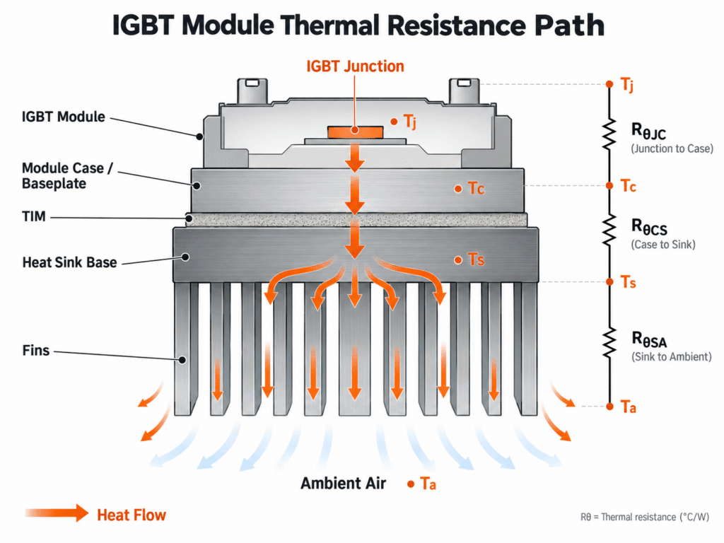
The cooling system must create an effective thermal path from the semiconductor junction, through the module baseplate and thermal interface, into the heat sink, and finally to the surrounding air or coolant.
For this reason, a good power electronics heat sink should be selected around the actual power loss, temperature limits, airflow, module layout, mounting conditions, available space, and manufacturing requirements.
This guide explains the key factors engineers and buyers should consider before finalizing an IGBT heat sink design.
Start With Power Loss, Not the IGBT Current Rating
The first question should be: how much heat must the cooling system actually remove?
An IGBT module may be rated for a high current or power level, but those ratings do not directly tell you the required heat sink size. The relevant value for thermal design is the actual power loss under the intended operating condition.
This normally includes conduction losses and switching losses from the IGBT, together with losses from the freewheeling diode or other devices inside the module. Operating frequency, current waveform, duty cycle, DC bus voltage, switching strategy, and junction temperature can all influence the final loss.
For an early heat sink evaluation, the designer should ideally provide:
- Total continuous power loss and any significant peak or transient load
- Maximum expected ambient temperature
- Target or allowable junction and case temperature
- IGBT module manufacturer and part number
- Number of modules mounted on the same heat sink
- Natural convection or forced-air cooling conditions
- Available cooling envelope and airflow direction
- Thermal interface and electrical insulation requirements
Without this information, heat sink selection becomes largely a geometric exercise rather than a thermal design process.
Build a Thermal Resistance Budget
A useful first step in IGBT cooling is to treat the heat path as a series of thermal resistances.
In simplified form:
IGBT junction → module case → thermal interface → heat sink → ambient air
The corresponding thermal resistances are commonly described as:
RθJC — junction-to-case thermal resistance
RθCS — case-to-heat-sink thermal resistance
RθSA — heat-sink-to-ambient thermal resistance
For a simplified steady-state estimate with one effective heat source:
RθSA,max = (Tj,target − Ta) / Ploss − RθJC − RθCS
where:
Tj,target = target junction temperature
Ta = maximum ambient temperature
Ploss = heat dissipated by the device
RθJC = junction-to-case thermal resistance
RθCS = case-to-sink interface thermal resistance
A Simple Example
For a simplified first-pass example, assume one effective device heat source dissipates 250 W under the design condition. The maximum ambient temperature is 45°C, and the engineering target is to keep the junction at or below 125°C.
If:
RθJC = 0.12°C/W
RθCS = 0.04°C/W
then the total allowable junction-to-ambient thermal resistance is:
(125 − 45) / 250 = 0.32°C/W
After subtracting the module and interface resistances:
RθSA,max = 0.32 − 0.12 − 0.04 = 0.16°C/W
The cooling system would therefore require a heat-sink-to-ambient thermal resistance of approximately 0.16°C/W or lower under the actual operating airflow.
Engineering Note: This is only a first-pass steady-state calculation. Real IGBT modules may contain multiple chips and diodes with different losses and transient thermal impedances. Multiple modules on one heat sink also interact thermally. Always use the module manufacturer's thermal data and validate the complete system under representative operating conditions.
Decide the Cooling Environment Before Designing the Fins
A heat sink should not be designed independently from the airflow around it.
Natural Convection
With passive cooling, warm air must be able to rise through the fin channels without excessive restriction. Fin spacing therefore tends to be more open, and the orientation of the fins becomes particularly important.
Adding more fins is not always beneficial. If the channels become too narrow, natural airflow can be restricted and part of the additional surface area becomes ineffective.
Forced-Air Cooling
Fans or blowers can support higher heat-transfer rates and often allow thinner fins and closer fin spacing. This makes high-density structures such as skived heat sinks attractive for compact power electronics.
However, fan airflow ratings should not be considered in isolation. The pressure drop through the heat sink, enclosure restrictions, fan position, air leakage, duct geometry, filters, and neighboring components all affect the airflow that actually passes through the fin channels.
For demanding systems, the fan and heat sink should therefore be evaluated as one active cooling system rather than as separate components.
The Heat Sink Base Is Part of the Thermal Design
IGBT modules often concentrate heat into an area much smaller than the overall footprint of the heat sink. Heat must therefore spread laterally through the base before the full fin area can be used effectively.
A base that is too thin may create a large temperature gradient directly below the module. Increasing base thickness can improve heat spreading, but simply making the base thicker is not always the best solution. It also increases weight, material cost, machining time, and thermal mass.
The correct base design depends on several factors, including module footprint, heat-source location, material conductivity, distance between multiple modules, total heat sink width, and fin arrangement.
For many applications, aluminum provides the best balance of conductivity, weight, manufacturability, and cost. When localized heat spreading becomes more demanding, copper or a hybrid structure may be considered.
Multiple IGBT modules also require careful placement. If several high-loss modules are installed too close together, their thermal fields can interact and raise the local heat sink temperature. Module spacing should therefore be considered during the mechanical layout rather than after the heat sink drawing has already been frozen.
Do Not Ignore the Module-to-Heat-Sink Interface
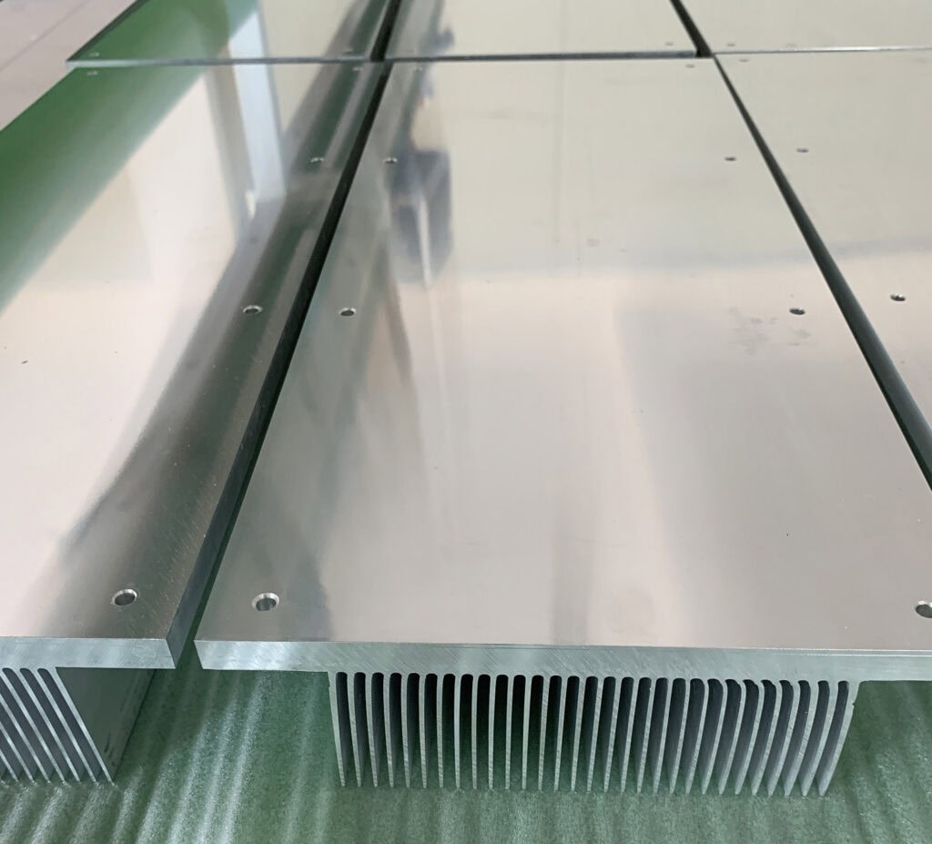
A high-performance heat sink can still perform poorly if the IGBT mounting interface is not properly controlled.
Even machined metal surfaces contain microscopic irregularities. Without an appropriate thermal interface material, small air gaps can significantly increase the contact resistance between the module baseplate and heat sink.
The following factors should therefore be considered together: mounting-surface flatness, surface roughness, thermal interface material, bond-line thickness, mounting-hole accuracy, screw torque, and module clamping method.
There is no single flatness or surface-roughness specification that should automatically be applied to every IGBT heat sink. Requirements vary between module manufacturers and package families. The safest approach is to define the mounting surface according to the specific power-module datasheet, mounting instruction, or approved customer drawing.
From a manufacturing perspective, it is also important to identify the critical mounting area clearly on the drawing. Requiring extremely tight flatness across the entire heat sink may add unnecessary machining cost when only the module-contact area requires precision control.
Thermal Interface Material
Thermal grease, phase-change material, thermal pads, or other TIM systems may be used depending on the module design and electrical requirements.
More TIM is not automatically better. An excessively thick interface can add thermal resistance, while insufficient material may leave voids or areas of poor contact. The correct material, thickness, application method, and mounting pressure should follow the module and TIM supplier's recommendations.
Surface Treatment Around the Mounting Area
Anodizing and other heat sink surface finishes may improve corrosion resistance or meet appearance and electrical requirements, but functional contact surfaces may require special treatment.
Depending on the design, module mounting areas, grounding locations, or electrical contact surfaces can be masked during finishing or machined afterward. These requirements should be identified before production so that machining and finishing sequences can be planned correctly.
Match the Manufacturing Process to the Thermal Requirement
There is no single manufacturing process that is best for every IGBT heat sink.
The correct choice depends on required thermal resistance, heat sink dimensions, airflow, fin density, base thickness, material, production quantity, machining requirements, and target cost.
In general, the following approaches are commonly considered.
| Cooling Structure | Best Fit | Main Advantages | Main Consideration |
|---|---|---|---|
| Extruded Heat Sink | Conventional air-cooled IGBT systems and repeat production | One-piece construction, economical, extensive existing profiles, easy CNC machining | Fin thickness, spacing, and aspect ratio are limited by extrusion feasibility |
| Skived Heat Sink | Compact systems requiring high fin density, especially with forced air | Thin, dense fins, one-piece base and fins, aluminum or copper options | Usually higher unit cost than a simple extrusion |
| Bonded Fin Heat Sink | Large inverter, converter, UPS, and industrial power assemblies | Large base sizes, tall fins, flexible spacing, and mixed-material options | Fin-to-base joining process must be properly controlled |
| Liquid Cold Plate | High heat flux or compact systems where air cooling is insufficient | Coolant can be brought close to the module mounting area | Higher system complexity, sealing, coolant, and pressure-drop requirements |
Extrusion Is Often the Starting Point
For many industrial IGBT applications, an aluminum extrusion is the first structure worth evaluating. It is cost-effective, mechanically robust, easy to machine, and especially attractive when an existing profile can meet the thermal and dimensional requirements.
Custom extrusion tooling can also make sense for repeat production when the required cross-section remains within practical extrusion limits.
Skiving Helps When Space Becomes Tight
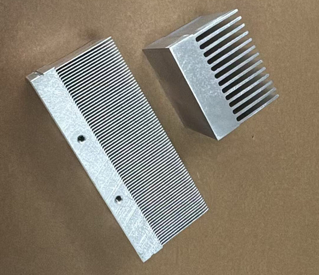
When the available width or cooling volume is limited, skiving can create significantly thinner and more closely spaced fins than many conventional extrusion designs.
This can increase available surface area, particularly when sufficient forced airflow is available. Copper skived structures are also possible when additional local heat spreading is required.
Bonded Fins Are Useful for Large Assemblies
Large industrial inverters and converters sometimes require heat sinks that are wider, taller, or more flexible than practical extrusion geometry allows.
Bonded-fin construction separates the design of the base and fins, providing more freedom in overall dimensions, fin height, spacing, and material combinations.
Know When Air Cooling Is No Longer Practical
There is also a point where continually increasing heat sink size, fin density, or fan power becomes inefficient.
When heat flux is high and installation space is limited, a liquid cold plate may provide a shorter and more effective thermal path.
The objective should not be to force every project into one production technology. It should be to find the simplest manufacturing approach that can reliably meet the thermal requirement.
For a broader comparison of these technologies, see our guide to choosing the right heat sink manufacturing process.
Consider Manufacturing Before Freezing the Drawing
Thermal performance is only part of a successful IGBT heat sink design. The part must also be manufactured, inspected, assembled, and produced repeatedly at an acceptable cost.
This is where early design-for-manufacturing review can prevent unnecessary changes later.
Do Not Apply Tight Tolerances Everywhere
IGBT module mounting areas may require controlled flatness and surface condition, but most fins and non-functional surfaces do not require the same precision.
Clearly separating critical and non-critical dimensions makes the drawing easier to manufacture and inspect while avoiding unnecessary CNC operations.
Plan the Machining Sequence
Power electronics heat sinks frequently require face milling, drilling, tapping, counterbores, pockets, mounting slots, sensor holes, cable clearances, or local fin removal.
These features should be considered when selecting the original extrusion, skived block, bonded-fin base, or cold plate structure. A thermally attractive geometry can become expensive if it leaves poor tool access or requires difficult fixturing.
Consider Fin Protection During Production and Shipping
High-density fins improve surface area but are also easier to damage. Thin skived fins and tall bonded fins require suitable handling, machining fixtures, cleaning, packaging, and transportation protection.
This becomes especially important for international shipments and repeat-production programs where dimensional consistency must be maintained from prototype through volume production.
Common IGBT Heat Sink Selection Mistakes
Selecting by outside dimensions alone. Two heat sinks with the same footprint can perform very differently because of base thickness, fin geometry, airflow resistance, material, and heat-source location.
Using a thermal-resistance value without checking its test conditions. A published heat sink rating may depend on a particular airflow, orientation, heat-source size, or test method. It should not automatically be treated as the performance inside the final enclosure.
Increasing fin density without considering airflow. More surface area helps only when air can effectively move through the channels.
Ignoring the module-to-sink interface. Flatness, TIM application, hole position, mounting pressure, and surface condition can significantly influence the real thermal path.
Making the entire heat sink excessively precise. Apply tight tolerances where they serve a thermal, mechanical, or assembly function rather than adding machining cost to non-critical surfaces.
Choosing the manufacturing process too late. Extrusion, skiving, bonded-fin construction, and liquid cooling have different geometric and economic limits. Selecting the production method early reduces redesign risk.
A Practical IGBT Heat Sink Selection Process
A reliable design normally starts with the IGBT module and operating conditions rather than the heat sink itself.
First, determine the actual power losses and temperature limits. Then establish the thermal-resistance budget and define whether natural convection, forced air, or liquid cooling is realistic.
Next, review heat spreading, module location, available space, mounting surface, thermal interface, and airflow. Only after these conditions are understood should the fin geometry and manufacturing process be finalized.
Finally, verify the design under representative operating conditions before moving into volume production.
At XINXIANG, we manufacture custom heat sinks for IGBT, MOSFET, SiC modules, inverters, motor drives, power supplies, energy systems, and other industrial power electronics.
Our manufacturing capabilities include aluminum extrusion, skiving, bonded-fin construction, CNC machining, forced-air assemblies, surface finishing, and liquid cold plates. This allows us to evaluate different manufacturing routes instead of forcing every project into the same heat sink structure.
If you already have a heat sink drawing, we can review it for manufacturability and quotation. If the project is still under development, send us your module information, heat load, dimensions, airflow conditions, and estimated quantity so we can evaluate a practical production approach.
Contact XINXIANG to discuss your IGBT or power electronics heat sink project.
Technical References
For additional technical guidance on IGBT module mounting, thermal resistance, and thermal interface requirements, refer to the following manufacturer documentation:
- Fuji Electric — IGBT Module Application Manual
- Infineon Technologies — Power Module Assembly Instructions
Specific mounting, flatness, surface roughness, thermal interface, and torque requirements can vary by module type. Always follow the latest documentation for the exact power module used in the application.
