Outdoor telecom equipment is expected to operate reliably for years while handling continuous heat generation from RF power amplifiers, processing electronics, power supplies, and other components.
For equipment such as remote radio units (RRUs), remote radio heads (RRHs), active antenna units (AAUs), and outdoor communication enclosures, thermal design is particularly challenging. High ambient temperatures, direct sunlight, limited installation space, and protection against dust and moisture can all influence the cooling strategy.
Unlike many indoor electronic systems, outdoor telecom equipment cannot always rely on fans or unrestricted ventilation. Heat must often travel from internal components through mounting interfaces, structural parts, and enclosure walls before it reaches external cooling surfaces.
A well-designed telecom heat sink must therefore be evaluated as part of the complete equipment structure, not simply as a collection of aluminum fins.
This guide explains the key considerations for designing outdoor telecom heat sinks, from thermal paths and environmental conditions to integrated enclosures, CNC machining, surface finishing, and manufacturing process selection.
Understand the Outdoor Operating Conditions First
Before designing the heat sink geometry, engineers should define the environment in which the telecom equipment will operate.
Outdoor installations can expose equipment to several thermal and mechanical challenges simultaneously:
- Continuous heat generation: RF and power electronics may operate for extended periods, creating sustained thermal loads.
- High ambient temperature: Hot weather reduces the temperature difference available for passive heat dissipation.
- Solar exposure: Direct sunlight can add heat to the external enclosure surfaces.
- Restricted ventilation: Sealed or highly protected equipment may not allow outside air to flow through the electronics compartment.
- Limited installation clearance: Nearby structures, brackets, walls, and other equipment can obstruct airflow around external fins.
- Environmental exposure: Rain, humidity, salt-containing atmospheres, dust, and temperature cycling can affect materials, finishes, and mechanical interfaces.
These conditions should not be evaluated independently. A heat sink that performs adequately in a laboratory at moderate ambient temperature may behave differently when installed on an exposed telecommunications tower or inside a densely packed outdoor equipment location.
Standards such as ETSI EN 300 019-1-4 provide a framework for identifying environmental conditions associated with stationary equipment at non-weatherprotected locations. The applicable requirements must still be defined for the actual installation and equipment design.
Build the Complete Thermal Path
For an outdoor telecom system, the most important thermal design question is not simply how much fin surface area is available.
It is: How does heat move from the electronic components to the outside environment?
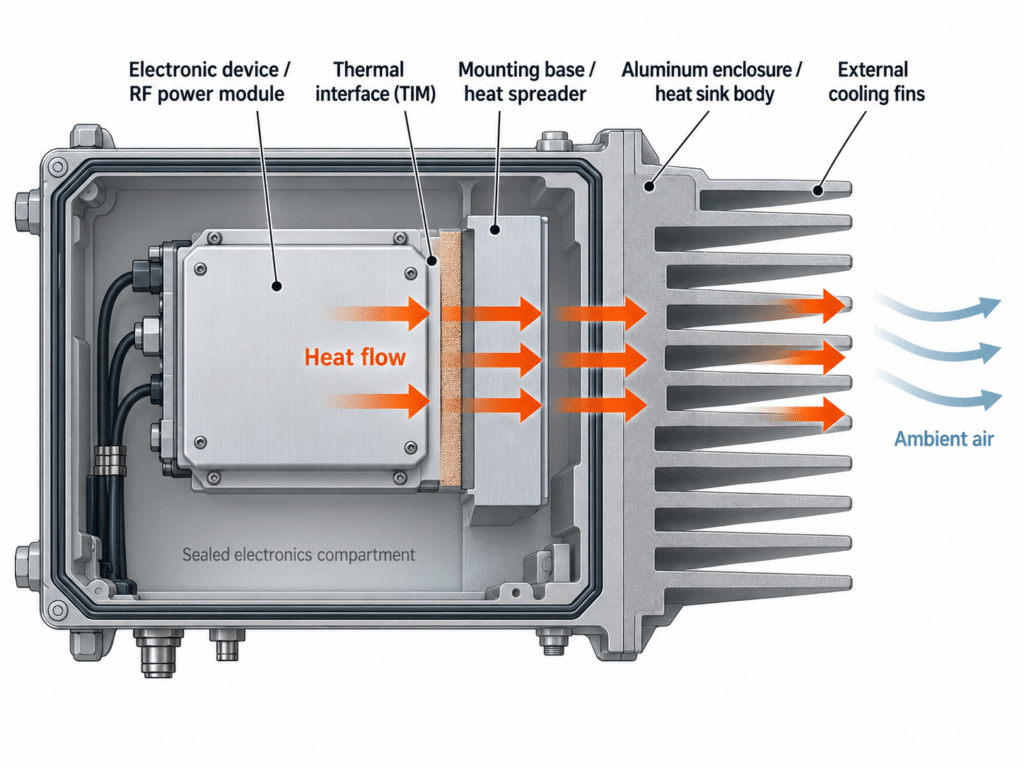
A simplified thermal path may look like this:
Electronic device → Thermal interface → Mounting base or heat spreader → Enclosure or heat sink → External fins → Ambient air
Each stage can introduce thermal resistance.
For example, an RF power device may generate significant heat over a relatively small contact area. That heat must spread through the mounting base before it can reach the much larger external finned surface.
If the mounting interface is poorly controlled, the enclosure wall is too thin for effective heat spreading, or the external fins are poorly positioned, the complete cooling system may underperform even when the nominal fin area appears sufficient.
Pay Attention to Localized Hot Spots
Outdoor radio equipment frequently contains several heat sources with different power levels and locations.
High-power RF transistors, amplifier modules, power-conversion components, and processors may each create localized hot spots.
When several devices share one aluminum housing or heat sink, their thermal fields can interact. The position of each component, base thickness, heat-spreading area, and distance between heat sources therefore become important design parameters.
Where aluminum alone cannot provide sufficient local heat spreading, copper inserts, heat pipes, or other heat-spreading structures may be considered, depending on the available space and mechanical requirements.
The final design should be evaluated against the actual component temperature limits and operating power losses, rather than relying only on the external enclosure temperature.
Account for Solar Exposure, Not Just Internal Heat
Solar exposure is one of the major differences between indoor and outdoor thermal design.
An enclosure installed in direct sunlight can absorb solar radiation through its external surfaces. Depending on the coating, orientation, surrounding conditions, and time of day, this additional heat can significantly affect the enclosure temperature.
For outdoor thermal design, engineers should therefore evaluate both internal electronic losses and external environmental heat gains.
For example, even if the electronics generate a relatively constant heat load, the enclosure may reach a higher temperature during periods of strong sunlight than during shaded operation at the same ambient air temperature.
Solar heating also makes surface finish selection more complicated.
A black surface may have high thermal emissivity, which can improve radiative heat rejection under certain conditions. However, it may also absorb more incoming solar energy. The final outdoor thermal performance depends on both solar absorptance and thermal emissivity, not color alone.
For exposed telecom equipment, the enclosure coating should therefore be evaluated against the actual sunlight conditions rather than selected solely to maximize thermal radiation.
Sealed Enclosures Need an Effective External Heat Path
Many outdoor communication devices require protection against water, dust, and other environmental contaminants.
Enclosure protection is commonly specified using an IP rating under IEC 60529. However, an IP rating describes protection against ingress; it does not indicate how effectively the enclosure dissipates heat.
A sealed electronics compartment may have little or no direct air exchange with the outside environment.
This creates an important thermal design distinction:
Air movement inside a sealed enclosure is not the same as heat rejection to the outside air.
An internal fan may help distribute heat among components or improve heat transfer to internal surfaces. However, the heat must still cross the enclosure boundary through conduction, an internal heat exchanger, or another designed thermal path before it can be rejected to the surrounding environment.
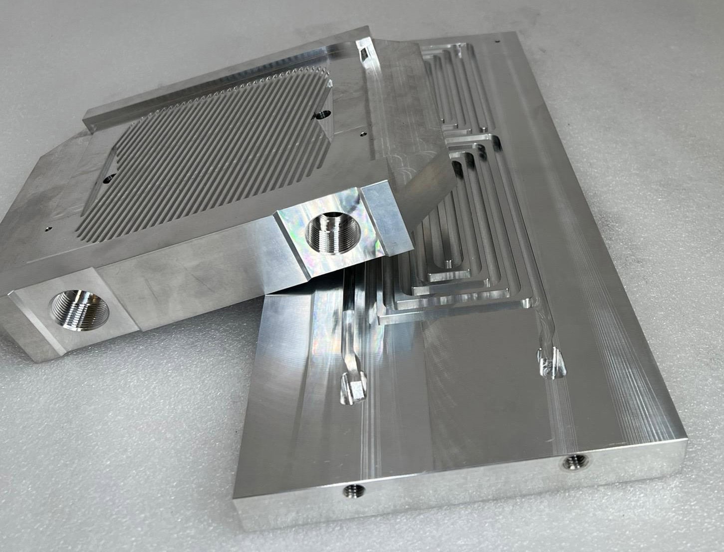
For compact outdoor radios, one practical approach is to transfer heat directly from the electronic components into an aluminum housing with external cooling fins.
This allows the electronics compartment to remain protected while the outside surfaces exchange heat with ambient air through natural convection and thermal radiation.
Integrated Finned Enclosures
In an integrated finned enclosure, the aluminum housing performs several functions:
- Supporting the electronic components and internal assemblies
- Providing a conduction path from heat-generating devices
- Spreading heat across the enclosure structure
- Providing external fin area for heat dissipation
- Supporting sealing, mounting, and mechanical protection requirements
Integrating these functions can reduce the number of separate components and interfaces in the assembly.
However, it also means that thermal, structural, sealing, and manufacturing requirements must be considered together from the early design stage.
Design External Fins for the Installed Orientation
For many fanless outdoor telecom products, natural convection is an important cooling mechanism.
As the external fins warm the surrounding air, buoyancy causes the heated air to rise and cooler air to replace it.
For straight-fin structures, orienting the channels to support this upward movement can improve natural-convection performance.
Fin geometry should be reviewed together with:
- Actual equipment mounting orientation
- Fin height and available surface area
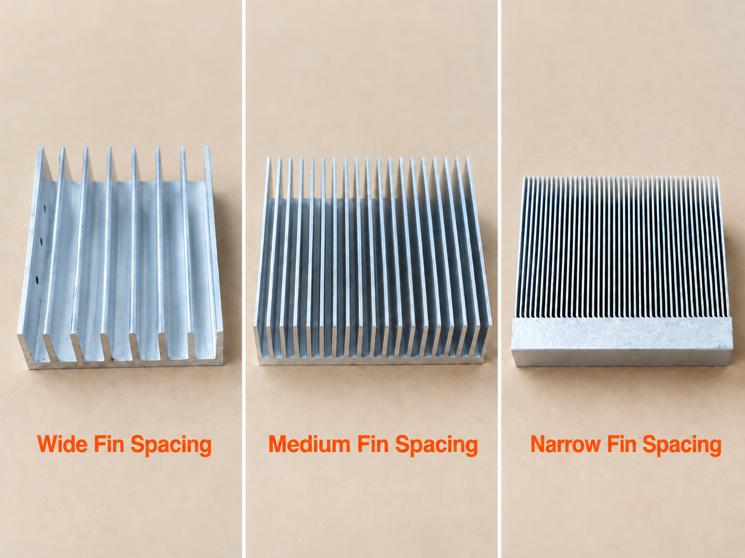
- Fin spacing and channel length
- External airflow clearance
- Nearby poles, mounting plates, walls, or other equipment
- Solar exposure and surrounding surface temperatures
More fins do not automatically improve cooling. Narrow channels can restrict buoyancy-driven airflow, especially when the available flow path is long or surrounding structures limit air movement.
We discuss this relationship in more detail in our guide to heat sink fin spacing.
Do Not Ignore Installation Clearance
A heat sink may perform well when tested in open air but lose cooling effectiveness when installed very close to a wall or mounting structure.
Restricted clearance can change the airflow around the fins, while nearby surfaces may also influence radiative heat exchange.
For this reason, prototype testing should represent the intended installation orientation and nearby obstructions as closely as practical.
If the system relies primarily on natural convection, see our passive heat sink solutions for additional cooling and manufacturing considerations.
Choose the Manufacturing Process Around the Enclosure Design
The manufacturing process influences the thermal geometry, mechanical structure, tooling investment, machining requirements, and production cost of an outdoor telecom heat sink.
The best process is not necessarily the one that creates the largest fin area. It is the process that produces the required thermal and mechanical features reliably at the expected production quantity.
Aluminum Extrusion
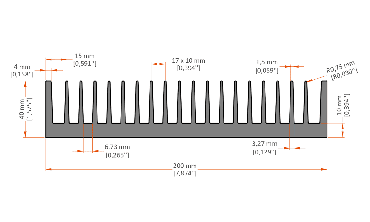
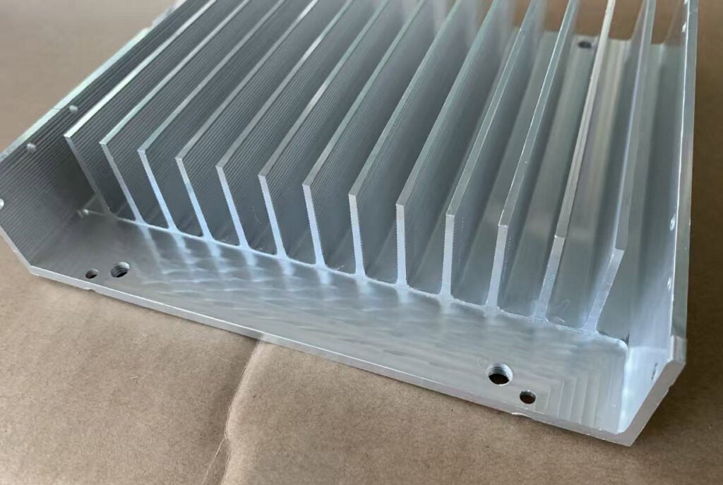
Extruded aluminum heat sinks are a practical choice when the required fins and base can be formed as a continuous cross-section.
Extrusion is especially attractive for designs with repeated straight-fin geometry, adjustable cut length, and relatively straightforward secondary machining.
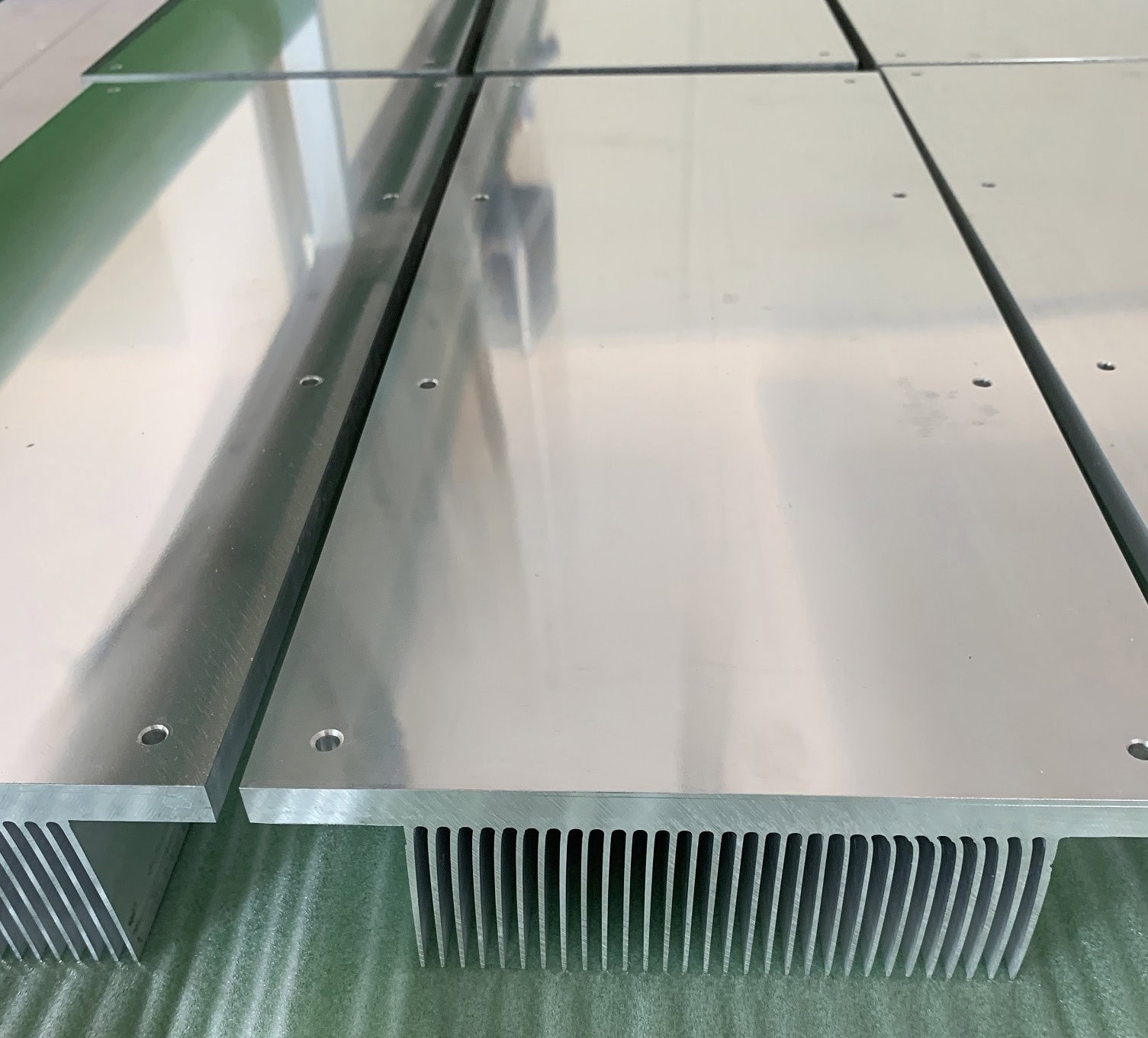
After extrusion, CNC machining can be used to create mounting surfaces, threaded holes, connector openings, pockets, and other application-specific details.
Existing extrusion tooling may also reduce initial development costs when a suitable cross-section is already available.
However, complex three-dimensional enclosure shapes, integrated bosses, and sealing structures may require substantial machining or additional components if extrusion is used.
Die Casting for Integrated Finned Housings
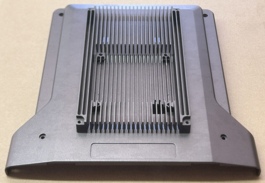
Die casting can be particularly useful when the heat sink is also a structural electronics enclosure.
A die-cast aluminum housing can integrate external cooling fins, mounting bosses, reinforcing ribs, connector areas, fastening features, and internal component supports.
For repeat-production outdoor radio equipment, this integration may reduce assembly complexity and the number of separate mechanical parts.
Die casting also provides flexibility for more complex three-dimensional shapes that would be difficult to create as a conventional extrusion.
However, casting design must account for wall thickness, metal flow, solidification, draft angles, tooling access, and possible casting defects. Critical thermal interfaces and sealing surfaces may still require CNC machining.
Where enclosure sealing is important, the casting and machining process should also be reviewed for porosity, leakage paths, and other manufacturing risks rather than assuming every as-cast wall will automatically provide the required sealing performance.
Skiving and Local Heat-Spreading Components
Skived heat sinks can create thin, closely spaced fins directly from a solid aluminum or copper base.
They may be useful for concentrated RF or power-electronics heat loads when additional fin surface is required within a limited footprint.
However, a high-density fin structure is not automatically the best solution for an externally mounted passive enclosure.
Fin spacing must still be appropriate for the available airflow, and any separate heat sink must have a suitable thermal connection to the enclosure or heat source.
Skiving, bonded-fin construction, copper inserts, and heat pipes can also be evaluated as parts of a larger thermal assembly when the enclosure geometry requires additional heat spreading or specialized cooling structures.
Manufacturing Considerations for Outdoor Telecom Heat Sinks
The following table summarizes how important outdoor design conditions influence the thermal structure and manufacturing requirements.
| Design Condition | Thermal Consideration | Manufacturing Consideration |
|---|---|---|
| High Ambient Temperature | Reduced temperature difference for heat rejection | Evaluate fin area, base heat spreading, and available cooling space |
| Solar Exposure | Additional heat absorption by exposed surfaces | Review coating properties, surface finish, and enclosure geometry |
| Sealed Electronics Compartment | Limited direct air exchange with the outside environment | Provide a conductive heat path to external fins and control sealing interfaces |
| Localized RF Hot Spots | Concentrated heat input and lateral heat-spreading requirements | Review base thickness, mounting flatness, and heat-spreading components |
| Restricted Installation Clearance | Possible obstruction of natural airflow around the fins | Check fin orientation, spacing, and the installed equipment envelope |
| Complex Integrated Housing | Thermal and structural functions combined in one part | Evaluate die casting, machining access, sealing surfaces, and tooling cost |
| Outdoor Corrosion Exposure | Long-term exposure to moisture, contaminants, and temperature cycling | Specify suitable surface treatment, protected interfaces, and material compatibility |
Plan CNC Machining Before Finalizing the Housing
Even when the primary aluminum structure is produced by extrusion or die casting, secondary CNC machining is often required to achieve the final mechanical interfaces.
For outdoor telecom equipment, several features deserve particular attention.
Heat-Source Mounting Surfaces
RF power devices and other heat-generating components may require controlled mounting flatness, surface finish, and hole positioning.
The required tolerances should follow the relevant component specifications and customer drawing. Applying unnecessarily tight tolerances to every non-functional surface can increase machining cost without improving thermal performance.
Sealing Surfaces and Gasket Grooves
Housing covers, gasket seats, and sealing interfaces may require controlled geometry and surface condition.
These features should be considered early because machining a long sealing surface on a thin or uneven enclosure can introduce fixturing and deformation challenges.
Machining Access and Clamping
External fins, deep cavities, thin walls, and irregular cast features can restrict cutter access or make the part difficult to hold securely.
Suitable machining datums and clamping areas should be considered during the original mechanical design.
In some cases, a small geometry adjustment can significantly simplify the machining process without materially changing the thermal concept.
Threads, Connectors, and Assembly Interfaces
Outdoor telecom housings may require tapped mounting holes, connector openings, cable passages, grounding points, brackets, and other assembly features.
These details should be checked for tool access, material thickness, sealing requirements, and possible interference with the thermal structure.
The main objective is to make the complete part manufacturable without introducing unnecessary machining operations or assembly complexity.
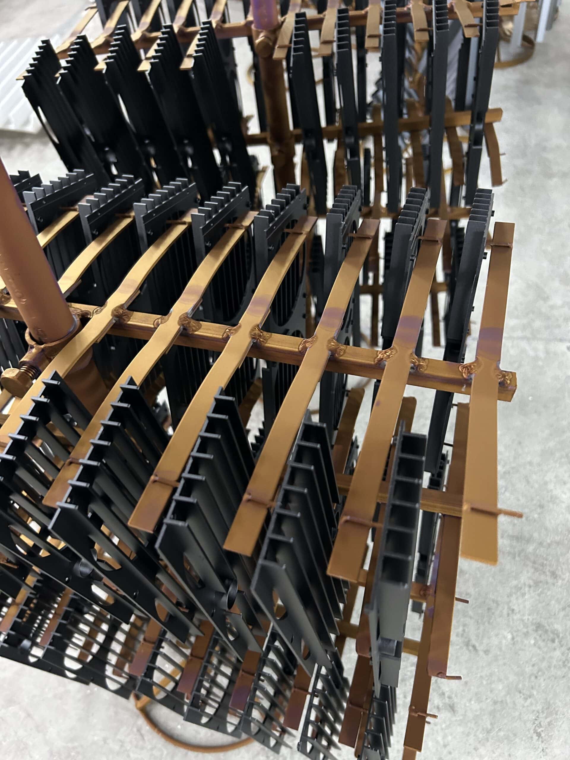
Specify Surface Finishing for the Outdoor Environment
Outdoor telecom heat sinks and aluminum housings may be exposed to humidity, rain, airborne contaminants, salt-containing atmospheres, and long-term temperature cycling.
The surface finish should therefore be selected according to the expected environmental conditions, aluminum alloy, assembly requirements, and thermal design.
Possible finishing options include anodizing, chemical conversion coating, powder coating, painting, and other project-specific treatments.
However, no single surface treatment is automatically suitable for every outdoor installation.
Consider Both Corrosion Protection and Thermal Behavior
Anodizing can provide useful surface protection for suitable aluminum components, while paints and powder coatings may offer additional environmental protection when properly specified and applied.
For outdoor thermal design, surface properties also influence solar absorption and thermal radiation.
A dark coating should not automatically be selected on the assumption that it will make the equipment cooler. Under direct sunlight, the additional solar energy absorbed by the surface may offset or exceed the benefit of improved thermal emission.
Coating selection should therefore consider the actual exposure, color, solar absorptance, thermal emissivity, corrosion resistance, and applicable environmental requirements.
Our heat sink surface finishes guide explains additional considerations for anodizing, conversion coatings, masking, and other finishing processes.
Protect Critical Functional Areas
Some areas of an outdoor telecom housing may require special treatment during finishing:
- Electronic component mounting surfaces
- Thermal contact interfaces
- Grounding and electrical contact points
- Gasket seats and sealing surfaces
- Threaded holes and fastening locations
- Connector and assembly interfaces
Depending on the finishing process and drawing requirements, these areas may need masking, controlled coating thickness, or machining after finishing.
Contact between dissimilar metals, such as aluminum and certain fasteners or copper components, should also be reviewed for galvanic corrosion risk under the expected moisture and environmental conditions.
Surface treatment is therefore part of the overall manufacturing plan, not simply the final cosmetic operation.
Validate the Design Under Realistic Operating Conditions
Thermal simulation and early calculations are useful for comparing design concepts, but they should not replace validation of the final equipment.
Outdoor telecom thermal performance depends on the complete assembly, including the electronics, mounting interfaces, housing, external fins, surface finish, and installation environment.
Before approving a design for production, representative testing should consider:
- Continuous and peak electronic heat loads
- Maximum specified ambient temperature
- Solar exposure where applicable
- Actual installation orientation
- Clearance around external fins
- Component and heat-sink temperature measurements
- Thermal interface materials and mounting conditions
- Relevant environmental, ingress-protection, and corrosion requirements
Thermal testing and environmental qualification may require different procedures. Passing an enclosure ingress-protection test does not by itself demonstrate that the electronics will remain within their allowable operating temperatures.
For repeat production, critical manufacturing characteristics such as mounting-surface flatness, sealing features, dimensions, coating requirements, and assembly interfaces should be clearly defined on the engineering drawing.
Common Outdoor Telecom Heat Sink Design Mistakes
Evaluating only the internal power loss. Direct solar exposure and high outdoor temperatures can significantly affect the final thermal operating condition.
Assuming a sealed enclosure cannot use external natural convection. A protected electronics compartment can still reject heat through conductive walls and external cooling fins.
Selecting fin geometry without considering orientation. Fin channels, installation clearance, and surrounding structures influence the actual natural airflow.
Using a high-density fin structure without checking airflow. More fin surface area does not always translate into lower operating temperatures.
Ignoring sealing surfaces during manufacturing planning. Gasket grooves, cover interfaces, and potential leakage paths should be addressed together with casting and machining requirements.
Selecting a black coating solely for cooling performance. Solar absorption and thermal emission must both be considered for equipment exposed to sunlight.
Testing only the heat sink instead of the complete equipment. Component placement, thermal interfaces, enclosure geometry, and installation conditions can change actual system performance.
What Information Should You Provide for Manufacturing Review?
When requesting a quotation for an outdoor telecom heat sink or finned enclosure, the following information is particularly useful:
- 2D drawings and 3D models of the heat sink or housing
- Equipment type, such as RRU, RRH, AAU, or outdoor radio enclosure
- Heat-source locations and estimated power dissipation
- Allowable component or mounting-surface temperatures
- Ambient temperature and installation conditions
- Solar exposure and equipment orientation, if known
- Required dimensions and weight limitations
- IP rating or other enclosure protection requirements
- Critical mounting, sealing, and CNC machining features
- Material and surface finish specifications
- Estimated production quantity
Complete project information helps identify whether extrusion, die casting, skiving, or another structure provides the most practical manufacturing solution.
If the heat sink drawing is already complete, a manufacturing review can focus on geometry, tolerances, material selection, machining sequence, finishing, tooling, and quotation.
For projects still under development, the mechanical envelope, heat-source arrangement, and operating environment are useful starting points for evaluating manufacturing feasibility.
Conclusion: Design the Thermal Path and the Housing Together
Designing an effective outdoor telecom heat sink requires more than maximizing aluminum fin area.
The thermal path must carry heat from the internal electronics to the outside environment while the enclosure continues to meet its mechanical, environmental, and assembly requirements.
High ambient temperature, solar exposure, fin orientation, mounting interfaces, base heat spreading, corrosion protection, and manufacturing feasibility all contribute to the final design.
For many outdoor communication products, an integrated aluminum finned enclosure provides a practical way to combine structural support and heat dissipation. Other designs may benefit from a separate extrusion, skived heat sink, heat-spreading component, or more specialized thermal assembly.
The best solution is the one that meets the complete thermal and mechanical requirements while remaining practical to manufacture, inspect, and produce consistently.
Need a Custom Outdoor Telecom Heat Sink?
XINXIANG manufactures custom aluminum heat sinks, finned housings, and thermal components for telecommunications and other industrial electronics applications.
Our capabilities include aluminum extrusion, die casting, skiving, CNC machining, surface finishing, and assembly support. We can review your drawing and manufacturing requirements to evaluate a practical production approach.
Whether your project requires an integrated finned enclosure, a machined extrusion, or a specialized thermal structure, send us your drawings, required quantity, and technical specifications for review.
Explore our custom telecom heat sink manufacturing capabilities, or contact XINXIANG to discuss your project.
Technical References
For additional technical guidance on outdoor telecommunications environments, enclosure protection, solar exposure, and thermal radiation, refer to the following resources:
ETSI — EN 300 019-1-4: Environmental Conditions for Telecommunications Equipment at Non-Weatherprotected Locations
IEC — IEC 60529: Degrees of Protection Provided by Enclosures (IP Code)
Electronics Cooling — Thermal Management of Telecommunications Cabinets
Actual thermal performance, enclosure protection, corrosion resistance, and environmental qualification depend on the complete equipment design, installation conditions, and applicable project specifications.